

What Counts as Utility-Scale Energy Storage
Utility-scale energy storage is grid-connected battery capacity rated in megawatts and megawatt-hours — commonly 1 MW and up — that stores electricity and returns it to the grid when it is most valuable, instead of sitting behind a single customer meter.
The label is about where the asset sits and who dispatches it, not about chemistry. A 5 MW / 20 MWh system feeding a transmission substation and a 2 MWh container co-located with a solar farm are both utility-scale; a 20 kWh home wall unit and a 100 kWh commercial cabinet are not. The working test most developers apply: it sits in front of the meter, a grid operator or offtaker can dispatch it, and its power electronics connect at medium voltage rather than at a building's low-voltage panel.
Two numbers then decide everything downstream. Power (MW) sets how fast the system can charge or discharge; energy (MWh) sets how long it can hold that output. Duration is simply energy divided by power — a 200 MW / 800 MWh system delivers 200 MW for roughly four hours. That single ratio explains why nominally identical hardware can serve a 30-minute frequency-regulation contract or a four-hour peak-shaving duty depending on how it is configured, and why "how big is it?" is always two questions, not one.
Tier | Connection point | Typical power / energy | Dispatched by |
|---|---|---|---|
Residential | Behind the meter, low voltage | 5–20 kWh | Household |
Commercial & industrial | Behind the meter, low voltage | 100 kWh to a few MWh | Site operator |
Utility-scale | Front of meter, medium voltage | 1 MW+ per unit / 2 MWh+, scaling to hundreds of MWh | Grid operator or offtaker |
Grid energy storage — sometimes called grid-scale energy storage or large-scale energy storage — is a broad category in which batteries, pumped hydro, and long-duration concepts all live, so the useful starting reference is the overview of grid energy storage technologies rather than any single product. For a working view of how utility-scale battery storage is packaged around those grid scenarios, the grid-scale solution overview lays out the operating scopes and system capability areas.
How a Utility-Scale Battery Storage System Works
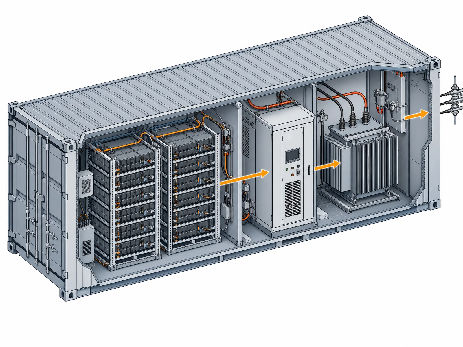
A utility-scale battery energy storage system (BESS) converts grid AC into DC to store energy in lithium-ion cells, then back into AC to deliver it — with a battery management system protecting the cells and a power conversion system (PCS) and energy management system (EMS) controlling the flow.
The architecture is a stack of scales. At the bottom, individual cells are grouped into modules, modules into racks, and racks into a container or cabinet. Cells and modules are commodity components; the engineering lives in how the layers above them are managed and cooled. A battery management system (BMS) monitors cell voltage and temperature and balances the pack, which is what turns thousands of cells into one safe, predictable bank — the same function that protects a home battery.
Above the battery sit the power electronics and controls. The PCS is the bidirectional inverter that moves energy between the DC battery bus and the AC grid; the medium-voltage transformer steps the output up to the level the grid connects at. The energy management system (EMS) is the layer that decides when to charge and discharge — arbitrage, peak shaving, frequency response — and reports state of charge and state of health back to an operator or a fleet dashboard. That decision layer is where the commercial value is actually captured; our EMS architecture whitepaper goes deeper.
The key point for scoping: a datasheet that lists only battery capacity hides the two subsystems — conversion and control — that most often determine whether a project performs as promised.
Containerized BESS: Why Utility-Scale Projects Ship in 20-Foot Containers
Most utility-scale batteries today arrive as pre-assembled, factory-tested containers: a standard 20-foot enclosure holding racks of cells, its own thermal management and fire suppression, shipped by truck and craned onto a concrete pad.
Containerization is the defining delivery model of grid-scale battery storage because it moves assembly, wiring, and testing off the site and into a factory. Two forms dominate, and confusing them is a common sourcing mistake:
- A DC battery block (battery-only). The container holds cells, BMS, cooling, and fire systems but no PCS — it outputs DC and needs a separately supplied inverter. These are the building blocks of very large projects, where one central PCS station serves many battery containers.
- An integrated container or cabinet (battery + PCS). The inverter is inside or attached, so the unit takes grid AC on one side and produces grid AC on the other — simpler to specify, faster to commission, and the norm for mid-size projects.
Unit energy has climbed steadily. A liquid-cooled 20-foot container now commonly carries on the order of 2 to 5 MWh, so a 100 MWh project — a realistic size for a large co-located or standalone plant — is a few dozen containers rather than hundreds of racks. That is why the industry quotes projects per container, not per cell; our walk-through of a 1 MWh battery container shows the math on a smaller unit, and the liquid-cooled container explainer covers why cooling moved from air to liquid as density rose.
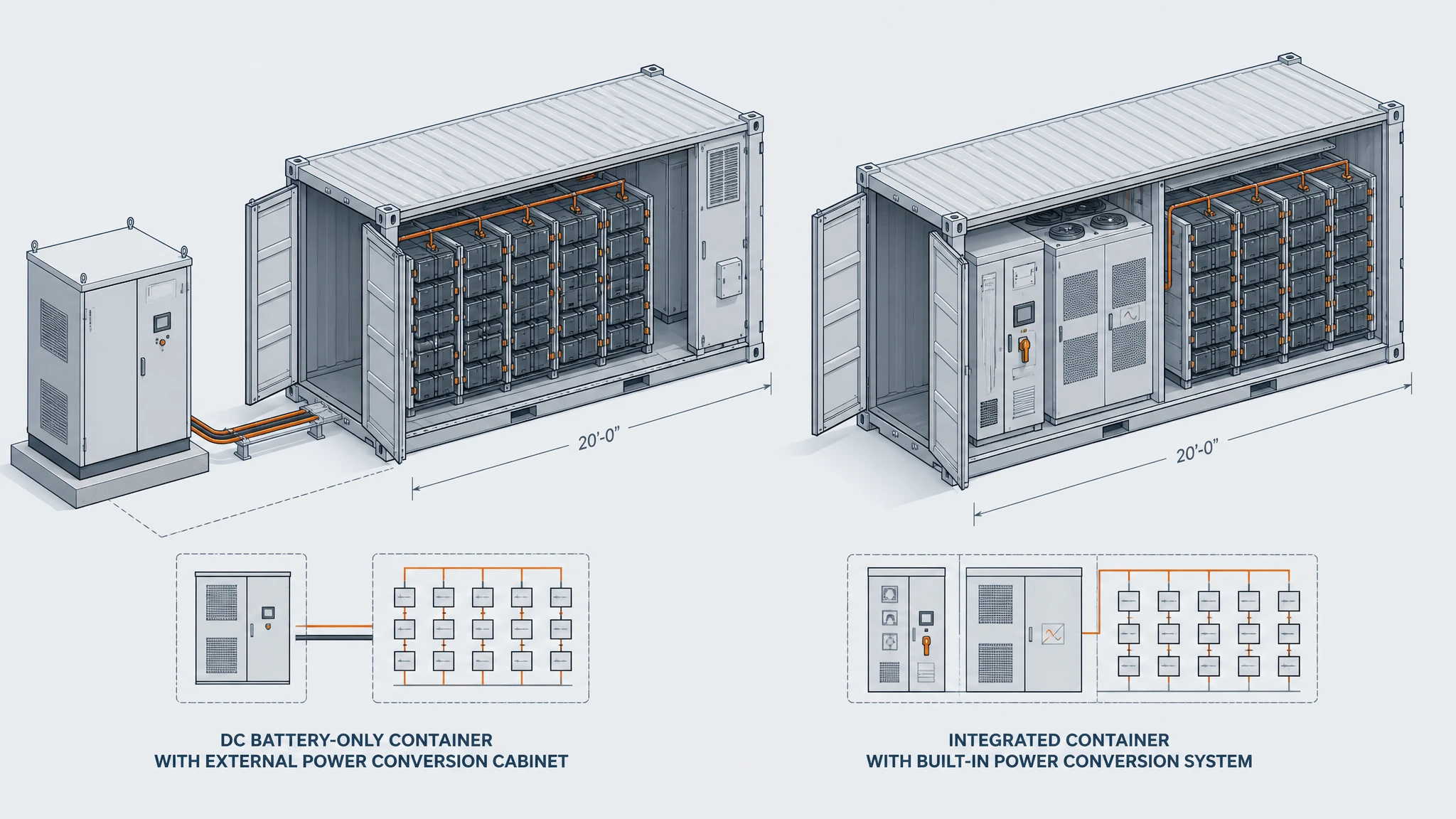
For a concrete reference, Hua Power's container line spans both forms. The 1 MW / 2.089 MWh liquid-cooled unit is an integrated 20-foot container with its own PCS and sub-20 ms off-grid transfer — the simpler, faster-to-commission option. The larger 5.015 MWh container is a battery-only DC block for longer-duration duty that pairs with an external PCS, the pattern very large projects use to concentrate conversion equipment. Either way, the container is a drop-in building block: an engineer picks the unit that matches the target duration, then repeats it as the project's megawatts require.
The Storage Technologies Behind Grid-Scale Systems (and Why LFP Leads)
Lithium iron phosphate (LFP) dominates new grid-scale batteries because it trades energy density for cycle life and thermal stability — precisely the properties a stationary asset cycled daily for 15–20 years needs.
The technology field is wider than one chemistry. Pumped-storage hydroelectricity remains the single largest installed form of grid storage worldwide, but it is geographically constrained and slow to build, so batteries have taken the growth. Within lithium-ion, two chemistries compete: nickel-rich NMC, which packs more energy per kilogram, and LFP, which is cheaper, longer-lived, and far less prone to thermal runaway. For a container bolted to a concrete pad, weight and volume matter far less than safety and cycle count, so the tradeoff falls decisively toward LFP — a shift visible across new utility-scale deployments and one we unpack in LFP vs other lithium-ion chemistries. Falling cost is what made the shift economic: lithium-ion battery prices have fallen about 99% since 1991 — roughly 19% for every doubling of production — according to Our World in Data.
Beyond lithium-ion, flow batteries and sodium-ion are advancing. Flow batteries decouple power from energy and suit multi-hour duty but carry lower round-trip efficiency; sodium-ion uses cheaper, less critical materials at the cost of energy density. Both are worth tracking, and neither yet displaces LFP for mainstream short-duration grid storage. For durations measured in days rather than hours — the "long-duration" problem — the honest answer today is that no single technology has won, which is why a growing share of grid batteries are deployed for the four-hour window they do best rather than stretched into roles they cannot fill.
The Specs That Actually Decide a Utility-Scale System
Five specifications separate a bankable grid-scale system from a datasheet: energy capacity and duration, C-rate, round-trip efficiency, cycle life and degradation, and thermal management — plus the site-facing ratings and the inverter's grid-support behavior.
Duration is the first filter, and it is set by the use case. The U.S. Energy Information Administration has documented that battery duration is dictated by how the system is used — shorter for frequency response, longer for shifting solar into the evening peak.
C-rate describes how fast the battery charges or discharges relative to its capacity. A 0.5C rating means a full charge or discharge in two hours; 0.25C means four hours. Higher C-rate needs more cells and more cooling to push the same energy, so it costs more per MWh — which is why matching C-rate to the contract, not maximising it, is the design goal. Our guide to choosing a battery C-rate works through the selection logic.
Round-trip efficiency (RTE) is the share of energy you get back versus what you put in, after conversion and thermal losses. Field numbers run below headline numbers; a realistic figure for a modern liquid-cooled container is 85–87%, not 95%, and the term is defined in our knowledge-base entry on round-trip efficiency. Because storage buys and sells electricity, RTE sets the price-spread the asset needs to be profitable.
Cycle life and degradation decide the project's useful life and therefore its economics. A bankable grid-scale cell today is specified in the range of ≥8,000 cycles to 80% state of health, cycling to roughly 90% depth of discharge (DoD). Degradation is not linear and accelerates at high states of charge, which is part of why grid batteries intentionally run narrower windows.
Thermal management is the spec that most often separates a container that lasts 15 years from one that does not. Liquid cooling holds cell-to-cell temperature uniformity within roughly ±2°C, extending calendar life and preserving efficiency in hot climates; air cooling remains adequate for lower-density cabinets and moderate environments. The break-even and the design tradeoffs are covered in liquid-cooled vs air-cooled BESS. For a 5 MWh container cycling daily in a hot climate, cooling is not a comfort feature — it is the difference between reaching the warranted cycle count and falling short of it.
Two more columns belong on the comparison sheet. Ingress and corrosion ratings — IP54 or IP55 enclosures with a C3–C4 corrosion class — determine whether the container survives a coastal or desert site. And grid-support capability (voltage and frequency ride-through, reactive power control, and grid-forming or virtual synchronous generator modes) determines whether the asset can stabilise a weak grid rather than merely follow it. For a worked example, the 5.015 MWh container specification lists cycle life, efficiency, IP rating, and UL-family certification (UL 1973, UL 9540, UL 9540A) plus NFPA 855 compliance side by side.
Spec | What it sets | Typical grid-scale value |
|---|---|---|
Duration (MWh ÷ MW) | How long the system discharges | 2–4 h typical; set by the use case |
C-rate | Speed relative to capacity | 0.25C–0.5C |
Round-trip efficiency | Energy recovered vs. energy put in | ~85–87% (field, not nameplate) |
Cycle life / DoD | Useful life and how hard it cycles | ≥8,000 cycles @ 80% SoH, ~90% DoD |
Thermal management | Cell temperature uniformity and life | Liquid-cooled to ±2°C; air where density is lower |
Where Utility-Scale Storage Earns Its Keep on the Grid
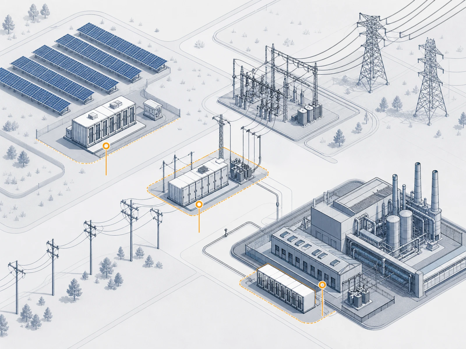
Utility-scale batteries earn revenue in five main places: co-located with generation, on the transmission and distribution network for peak regulation, providing frequency regulation and other ancillary services, deferring grid upgrades, and supporting black start.
Co-location with renewables is the fastest-growing pattern. Pairing storage with a solar or wind plant lets the farm smooth its output, avoid curtailment when the grid cannot absorb generation, and shift production into higher-priced hours. The U.S. Energy Information Administration classes batteries as a fast-growing secondary electricity source on the grid, and co-location is one of the structures driving that build-out.
Peak regulation and peak shaving is the revenue a battery earns by charging when power is cheap and discharging into the evening peak. On the network, it reduces strain on transmission and distribution assets and can defer expensive upgrades; behind large loads, it cuts demand charges. The mechanics are the same at both scales — our guide to grid-side peak regulation and the commercial peak-shaving breakdown cover the two sides.
Frequency regulation and ancillary services are where batteries beat every competing asset on speed. Responding in milliseconds, a grid battery can hold frequency within tight limits, provide spinning reserve, and firm up voltage. Real projects show the scale — the California battery storage project is a grid-scale example of storage built to firm a high-renewable network, and the storage industry association American Clean Power tracks employment and tax-revenue effects of these builds.
Black start and grid resilience close the loop: a battery can energise a network section without an external power source, restarting a system after an outage. Resilience sits alongside the revenue services above as a core grid role, and the U.S. Department of Energy's energy storage programme funds research and demonstration aimed at extending what grid-scale storage can do.
Safety, Standards, and Grid-Code Compliance
A grid-scale battery has to clear two independent rule-sets: product safety standards and the connecting grid operator's codes — passing one says nothing about the other.
On the product safety side, the core family is IEC 62619 (industrial lithium cells and batteries), IEC 63056 (batteries for electrical energy storage systems), and UL 1973 (stationary battery systems), with UL 9540 as the system-level safety standard and UL 9540A the test method for evaluating thermal runaway fire propagation. Fire protection and installation then follow NFPA 855 in the U.S., the standard for stationary energy storage installation. Our UL 9540A battery cabinet primer explains what that testing actually measures and why it matters to insurers and authorities having jurisdiction.
On the grid-connection side, the operator's code governs how the inverter behaves at the point of common coupling — voltage and frequency ride-through, reactive power, and anti-islanding. The relevant set depends on market: G99 in the UK, VDE-AR-N 4105/4110/4120 in Germany, EN 50549 across much of the EU, CEI 0-21 in Italy, and equivalents elsewhere. Because compliance is jurisdiction-specific and often the longest lead item, it is worth pinning down early — our guide to EU grid-connection compliance walks through the European requirements.
Two facts follow for anyone scoping a project. First, fire safety is now engineered, not merely asserted: gas detection, deflagration venting, aerosol or FK-5-1-12 suppression, and thermal-runaway testing all belong on the specification. Second, certifications travel — a container certified to the IEC and UL families clears the product bar, while the grid code still has to be met market by market, which is what the site operator actually checks.
Sizing, Costing, and Procurement: How a Utility-Scale Project Gets Scoped
A project is scoped backwards from its use case: the required power and duration set the energy capacity, the site and grid code set the enclosure, and the interconnection queue and levelized cost decide whether the economics close.
The sequence rarely varies. Start with the service: how many megawatts must the asset deliver, and for how long? That fixes the MWh. Then fix the site: an outdoor pad, an indoor room, a coastal or desert climate each narrow the enclosure and cooling options. Then face the interconnection queue, which in many markets is the true critical path; a battery that is technically ready but queued for years earns nothing. Finally, test the economics against a levelized cost of storage (LCOS) that accounts for round-trip losses, degradation, and the charging cost — the metric our explainer on LCOS for utility storage works through.
Because that chain has many places to go wrong, the practical answer is a disciplined procurement process: verify the datasheet against test evidence, confirm the certifications actually cover your market, and check the supplier's ability to support a fleet over 15–20 years. Our C&I BESS procurement guide sets out the checklist, and it applies almost unchanged at utility scale.
For scale context, the suppliers that matter here are the ones with volume behind them. Hua Power, a Shenzhen-based manufacturer founded in 2015, has fielded 400+ storage projects and lists reference installations including a 10 MW / 69 MWh plant in California and a 19.2 MW / 46.9 MWh project in Indiana, with an EMS platform (Visual Energy) covering fleet control. The point for a buyer is not the logo — it is that a container is only as bankable as the company that will still be servicing it in year twelve.
FAQ
How big is a utility-scale battery?
Utility-scale starts around 1 MW of power and typically runs to hundreds of MW. Energy scales with duration: at four hours, a 100 MW system is a 400 MWh installation — roughly 80 containers at 5 MWh each. Project size is quoted in MW (power) and MWh (energy), never in one number.
How long do utility-scale batteries last?
A bankable grid-scale system is specified for roughly 8,000-plus cycles to 80% state of health — about 15 to 20 years of daily cycling. Calendar life depends heavily on thermal management and how narrow a state-of-charge window the operator runs; liquid-cooled containers hold their capacity longer in hot climates.
How much does utility-scale battery storage cost?
Cost is falling fast and is best judged per MWh of usable energy, not per container. Levelized cost of storage (LCOS) — which folds in equipment, round-trip losses, degradation, and charging cost — is the number that determines whether a project pays back. Because prices move quarterly and vary by market, treat any figure older than a season as indicative only.
What is the difference between utility-scale and commercial (C&I) storage?
The dividing line is dispatch and connection point, not size alone. Utility-scale storage is front-of-meter and dispatched by a grid operator or offtaker, connecting at medium voltage. Commercial and industrial storage sits behind a single site's meter, connects at low voltage, and is optimised for that site's demand charges and resilience.
Which companies make utility-scale battery storage?
The market spans pure-play battery manufacturers, integrated system providers, and the power-electronics firms that supply inverters. What differentiates suppliers at utility scale is container-level integration, third-party certification, grid-code coverage for your market, and long-term service capability — not cell brand alone.
Is utility-scale energy storage the same as long-duration storage?
No. "Utility-scale" describes where and how the asset is deployed; "long-duration" describes how long it discharges. Most utility-scale batteries today discharge for two to four hours. Longer durations — eight hours and up — are a separate, still-emerging category where flow, sodium-ion, and long-duration technologies compete with pumped hydro.
Key Takeaways and Next Step
Utility-scale energy storage is a system, not a product. The MWh follows from the service you are buying, the container follows from the site, the certifications follow from your market, and the economics follow from all three. Get the order right and the specification almost writes itself: fix the duration and C-rate, insist on real cycle-life and thermal evidence, and confirm both product safety and grid-code compliance before you commit.
If you are scoping a project, start with the grid-scale solution overview to map your operating scenario to a system capability set, then take the specification questions above to a supplier who can answer them with test data rather than adjectives.