

A battery energy storage container is a deceptively simple object: a steel box, some racks of lithium cells, and — the part almost nobody puts on the front of the datasheet — a cooling system working full-time to keep those cells alive. Get the cooling right and a 20-foot box quietly delivers megawatt-hours for fifteen years. Get it wrong and the same box loses capacity, wastes energy on its own air conditioning, and edges toward the one failure mode the whole industry is built to avoid.
The field has moved fast. A few years ago "container cooling" meant one thing — an HVAC unit blowing cold air down the aisle. Today you'll see cold-plate liquid loops, immersion tanks, phase-change buffers, and hybrids, each solving the same physics problem a different way. This guide maps the full landscape of battery container cooling technology — what each approach is, how it works, and where it fits — so you can read a supplier's spec sheet knowing what the cooling architecture is actually buying you.
The short version: Lithium cells want to sit in a narrow, uniform temperature band (~15–35 °C). Every cooling technology is a different way to hold that line as you pack more energy into the box and cycle it harder. Forced-air is simple and cheap but thermally weak; cold-plate liquid is now the mainstream default for dense, hard-working containers; immersion and two-phase push temperature uniformity and safety further but are still maturing; PCM and heat pipes are passive helpers, rarely the whole answer. The right choice is set by three things: how hard you cycle (C-rate), how hot your site gets, and how much energy density you need per square meter.
Cooling technology | How it moves heat | Temperature uniformity (ΔT) | Parasitic load | Maturity / best fit |
|---|---|---|---|---|
Forced-air / HVAC | Fans + air conditioner push conditioned air across modules | Wider (gradients across the rack) | Higher | Mature — small, low-C-rate, mild-climate systems |
Cold-plate liquid | Pumped water-glycol through plates against modules | Tight (~±2 °C achievable) | Low | Mature — the mainstream default for MWh containers |
Immersion (single-phase) | Cells submerged in flowing dielectric fluid | Very tight | Low | Emerging — high density, strong fire performance |
Immersion / pumped two-phase | Dielectric fluid boils & condenses at the cell | Near-isothermal | Very low | Early — highest performance, least field data |
Phase-change material (PCM) | Solid-to-liquid melt absorbs heat spikes passively | Buffers peaks | ~Zero (passive) | Niche — usually paired with active cooling |
Heat pipes / hybrid | Passive two-phase spreading, or air+liquid combos | Varies | Low | Situational — supplements a primary system |
ΔT and parasitic figures are typical industry ranges; your project numbers depend on cell layout, duty cycle, and climate.
Why cooling is the decision that shapes a container
Every technology below traces back to one fact of physics: a battery loses a fraction of the energy it moves as heat, and that heat scales with how hard you cycle it. The cooling system's whole job is to carry that heat away fast enough — and evenly enough — to keep every cell in its safe window.
Three consequences follow, and they're the reason cooling deserves more scrutiny than its line on the datasheet suggests:
- The Goldilocks window. Lithium-iron-phosphate (LFP) cells are happiest around 15–35 °C. Run them hotter and they age faster; run them cold and they lose usable power. Cooling holds that band regardless of what the weather outside the container is doing.
- Uniformity matters as much as temperature. A pack is only as healthy as its hottest module. Heat drives aging on roughly an Arrhenius relationship — the reaction rate climbs steeply with temperature, so a module running 8–10 °C hotter than its neighbors ages disproportionately faster, its capacity drifts, and the whole series string is dragged down to match it. This is why temperature spread (ΔT) across the cells — not just the average — is the number that separates cooling technologies. A cold-plate liquid loop can hold cells within roughly ±2 °C; forced air rarely gets close. (Duty cycle drives how much heat there is to spread in the first place — see battery C-rate selection.)
- Cooling costs you energy — the parasitic load. Every watt spent running fans, pumps, or compressors is a watt you can't sell or use. This "parasitic" or auxiliary load is where weak cooling quietly bleeds a project: an air-cooled system can spend on the order of 3–5% of throughput on cooling, climbing toward 8–12% in a 40 °C ambient, while a well-designed liquid loop typically sits around 1–2% and barely moves with outside heat. (These percentages are typical industry ranges, not Hua Power measurements — your figures depend on cell layout, duty cycle, and climate.)
Hold those three ideas — window, uniformity, parasitic load — and every technology below becomes easy to place.
The full landscape of battery container cooling technology
Most guides stop at "air vs liquid." That binary made sense a decade ago; today it hides most of the field. Here is the complete taxonomy, from the workhorse to the frontier.
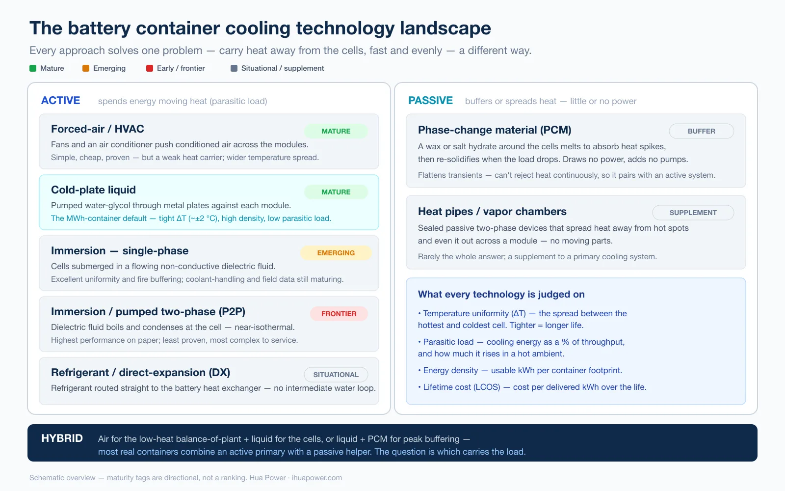
The cooling landscape splits into active systems that spend energy moving heat and passive systems that buffer or spread it — most real containers combine them.
Forced-air / HVAC cooling
The original approach, and still the right one for the right job. An air-conditioning unit chills the air inside the enclosure; fans push it across the battery modules and back. Air is free, the hardware is simple and proven, and there's no coolant to service — you change filters and you're done.
Its weakness is physics: air is a poor heat carrier — its heat capacity by volume is a tiny fraction of water's — so it needs a lot of moving air and struggles to cool the cells buried in the middle of a dense rack as well as the ones near the vents. That leaves a wider temperature spread, a bigger cooling-energy bill in hot climates, and a hard ceiling on how densely you can pack the box. For a small, gently-cycled container in a mild climate, none of that may matter. Hua Power's air-cooled line — from the HC-UPSAP112 (50 kW / 112.5 kWh) cabinet up to the HC-UPSAP1205 1,205 kWh 20-ft container with its 25 kW HVAC unit — is built for exactly those jobs.
Cold-plate (direct-to-plate) liquid cooling
The mainstream default for modern MWh containers, and the reason the container class has moved so fast. A pump circulates a water-glycol coolant through metal cold plates pressed against the battery modules; a heat exchanger dumps the collected heat outside. Because the coolant touches the heat at its source and carries far more of it per pass, the system holds every cell in a tight, uniform band even when the box is packed dense and cycling hard.
That uniformity is where the advantages compound: higher energy density, lower parasitic load, and longer sustained life. The headline is density — in the same 20-foot footprint, an air-cooled container lands near 1.2 MWh while a liquid-cooled one now routinely holds 2 MWh and up. Industry reporting has established liquid cooling as the preferred temperature-control architecture for modern MWh-scale BESS containers. Solar Power World notes that essentially every new 5 MWh LFP container now ships with liquid cooling rather than conventional HVAC. Hua Power's liquid line runs from the **HC-UPSAP261L cabinet (125 kW / 261 kWh) through the HC-UPSA2089L container (2.089 MWh) to the HC-UPSB5010L (5.01 MWh), holding cell ΔT to about ±2 °C.
Immersion cooling (single-phase)
Instead of pressing plates against the modules, immersion cooling submerges the cells directly in a non-conductive dielectric fluid — synthetic esters, hydrofluoroethers, or silicone oils. Because every surface of every cell is in contact with the coolant, temperature uniformity is exceptional and the fluid can also act as a fire buffer. Jensen Hughes notes that dielectric immersion can limit thermal runaway to a single cell, interrupting the cell-to-cell propagation that turns one bad cell into a container fire, while using less auxiliary power than plate cooling.
The catches are real and worth stating plainly: leaks matter more when the whole pack is bathed in fluid, some fluids are flammable, maintenance and contamination monitoring get harder, and the industry still lacks long-run field and UL 9540A data for stationary BESS. Immersion is a genuine contender for high-density, safety-critical sites — but it's emerging, not yet the default.
Pumped two-phase immersion cooling (P2P)
The frontier. In a two-phase system the dielectric fluid boils at the hot cell surface and condenses as it gives up heat — and a fluid's latent heat of vaporization carries enormously more energy than simply warming it up would. The result is near-isothermal operation: the whole module sits at essentially one temperature. Thermal specialists such as Advanced Cooling Technologies build **pumped two-phase and loop-thermosyphon systems** precisely for this uniformity and responsiveness. It's the highest-performing option on paper — and the least proven in the field, the most expensive, and the most complex to service. Watch it; don't spec your 2026 project around it.
Phase-change material (PCM)
PCM cooling is passive: a material (often a paraffin wax or salt hydrate) packed around the cells melts when things get hot, soaking up heat as latent energy, then re-solidifies and releases it when the load drops. It draws no power and adds no pumps, and it's excellent at flattening short thermal spikes — a burst of fast cycling, a transient. What it can't do is reject heat continuously, so in a hard-working container PCM is a buffer paired with an active system, not a standalone cooling technology.
Heat pipes, refrigerant-DX, and hybrids
A few more you'll encounter. Heat pipes and vapor chambers are sealed passive two-phase devices that spread heat away from hot spots — useful as a supplement. Refrigerant / direct-expansion (DX) cooling routes a refrigerant directly to the battery heat exchanger, skipping the intermediate water loop. And hybrid designs deliberately combine approaches — air for the low-heat balance-of-plant, liquid for the cells; or liquid plus PCM for peak buffering. In practice most real containers are hybrids of some kind; the question is which technology carries the primary heat load.
Inside a container liquid-cooling loop
Because cold-plate liquid is the workhorse of the MWh class, it's worth opening the box on how a container-scale loop is actually built — this is where suppliers quietly differ and where the datasheet goes quiet.
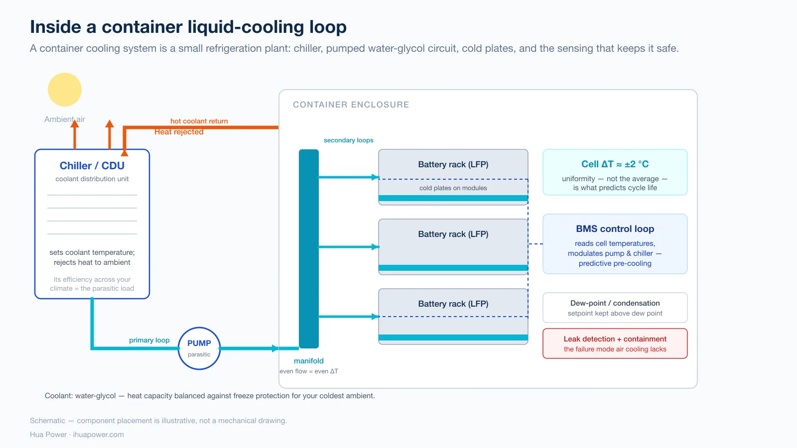
A container cooling loop is a small industrial refrigeration plant: a chiller or coolant distribution unit, a pumped water-glycol circuit, cold plates on every module, and the sensing and containment that keep it safe.
- The chiller / coolant distribution unit (CDU). A container-scale system usually has an outdoor chiller (or a liquid-cooling ECU/CDU) that rejects heat to ambient and sets the coolant temperature. Its capacity and its efficiency across your local temperature range are what determine the real-world parasitic load.
- Primary and secondary loops. Coolant is pumped from the CDU through a distribution manifold, then splits into branches feeding the cold plates on each rack. Even flow distribution across branches is what actually delivers the ±2 °C uniformity — poor manifold design starves the far modules.
- Coolant chemistry. A water-glycol (ethylene- or propylene-glycol) mix balances heat capacity against freeze protection; the glycol ratio has to match your coldest ambient, and the fluid needs periodic replacement and correct end-of-life disposal.
- Condensation / dew-point control. Running coolant below the dew point inside a humid enclosure risks condensation on cold surfaces — a real design constraint that good systems manage with setpoint control and sealing.
- Leak detection and containment. The coolant loop is the one failure mode air cooling doesn't have, so a serious liquid system includes leak detection, isolation, and containment — non-negotiable for anything you'll leave unattended.
- The BMS control layer. None of this runs open-loop. The battery management system (BMS) reads cell temperatures and modulates pumps and chiller setpoints — increasingly with predictive control that pre-cools ahead of a known high-C-rate window rather than reacting after cells heat up.
When a supplier can talk fluently about manifold balancing, dew-point margin, and leak containment — not just "liquid-cooled, 5 MWh" — you're talking to someone who builds the loop rather than buys it.
The parameters that actually compare cooling systems
Marketing language ("advanced," "efficient") won't help you choose. Five measurable things will.
- Temperature uniformity (ΔT). The spread between the hottest and coldest cell under load. Tighter is better; it's the leading indicator of sustained cycle life. Cold-plate liquid targets ~±2–3 °C; immersion can go tighter; air is typically several degrees wider.
- Parasitic / auxiliary load. Cooling energy as a percentage of throughput — and, just as important, how much it rises in a hot ambient. Liquid's near-flat curve versus air's steep one is the whole efficiency argument.
- Energy density. Usable kWh per container footprint. This is the clearest liquid-over-air win — roughly 1.7× the energy in the same 20-ft box (e.g. Hua Power's air-cooled HC-UPSAP1205 at 1,205 kWh vs the liquid-cooled HC-UPSA2089L at 2,089 kWh). If land or floor space is scarce, density converts directly into capacity or a smaller site. (For turning capacity into a container spec, see how to choose a 1, 2 or 5 MWh battery container.)
- Sustained cycle life. Both of Hua Power's architectures reach ≥8,000 cycles at 80% state-of-health on the test bench; the difference shows in the field, where tighter temperature control sustains that life under hard, hot duty. Industry data — not a Hua Power measurement — puts the real-world gain on the order of 10–30% more delivered cycles under demanding conditions.
- Lifetime cost (LCOS/TCO). The metric that most often flips the verdict. Levelized cost of storage (LCOS) divides total lifetime cost — CAPEX plus O&M, charging energy, and mid-life augmentation — by total energy delivered. Liquid costs more upfront but wastes less on cooling, ages slower, and defers augmentation, which is why it frequently wins on cost per delivered kWh even when it loses on sticker price.
Air vs liquid: the short version
If your project has already narrowed to the two mainstream options and you just need to make the call, the decision comes down to duty and climate: choose liquid when the system is dense, cycles hard, sits in a hot climate, or heads toward utility scale; choose air when it's small, lightly cycled, in a mild climate, and upfront cost rules. That trade-off deserves its own treatment — see the full head-to-head in liquid-cooled vs air-cooled BESS, which works through density, parasitic load, cycle life, and a TCO worked example.
Cooling and fire safety
Thermal management and fire safety are two ends of the same rope. The better you hold cell temperature and uniformity, the less likely you are to reach thermal runaway — the self-sustaining exothermic chain reaction that turns one failing cell into a container fire — in the first place. And the cooling architecture shapes how a system contains an event if one starts: liquid and immersion designs can double as heat sinks that cool a runaway cell and slow cell-to-cell propagation. Hua Power's liquid-cooled cabinets pair the coolant loop with a water-based compartment suppression system for exactly this reason. (For the engineering trade-offs between sprinkler, water-mist, and gaseous suppression, POWER magazine's overview is a good primer.)
Cooling never replaces certification, though. Whatever the architecture, the system should carry the right standards for your market:
- UL 9540A thermal-runaway fire-propagation test data and NFPA 855 installation compliance for North America — note that the 2026 edition of NFPA 855 tightens large-scale fire-testing requirements, so confirm your supplier's documentation is current. (UL's own primer on UL 9540A and NFPA 855 explains how the test feeds the install code.)
- IEC 62619 / 63056 / 62933 for cell safety, ESS safety, and system-level electrochemical safety in IEC markets.
Hua Power's liquid-cooled containers are certified to IEC 62619, 63056, 62477 and the IEC 61000-6 EMC standards, and the US-market HC-UPSB5010L carries the full North American stack — UL 1973, UL 9540, UL 9540A, UN 38.3, NFPA 855, NEC 2023 and NFPA 70E. For the market-by-market picture, see our EU grid-connection compliance guide.
Where the technology is heading (2025–2026)
Three currents are worth tracking as you plan:
- Density keeps climbing. The 20-foot container that held ~2 MWh a few years ago and 5 MWh recently is already pushing past 6 MWh — Powin's Pod Max, for example, put 6.26 MWh into a 20-ft liquid-cooled box. Every step up leans harder on the cooling system.
- Cell-to-pack and tighter integration. Removing module-level packaging packs cells closer together, which raises heat density and makes uniform cooling — and cooling that's designed into the pack rather than bolted on — even more decisive.
- The efficiency squeeze. As liquid loops, better controls, and predictive BMS logic mature, the energy spent on thermal management keeps falling — the direction of travel is toward cooling that costs a couple of percent of throughput, not eight. Immersion and two-phase sit at the experimental edge of that same push.
The through-line: as containers get denser and cycle harder, cooling stops being a component and becomes the enabling technology. The vendors who win the next few years are the ones treating it that way.
How to choose — and how Hua Power approaches it
Matching a cooling technology to a project comes down to the three variables this guide keeps returning to: how hard you cycle (C-rate), how hot your site gets, and how much density you need. Low duty, mild climate, tight budget, modest size → air still makes sense. Dense, hard-cycling, hot, or utility-scale → liquid, today, is the default; immersion and two-phase are worth a conversation for the most demanding or safety-critical sites. Turning that into an exact model, capacity, and compliance package is a project-specific exercise — the C&I BESS procurement guide lists what to lock down first.
Hua Power is an energy storage system integrator founded in 2015, with 400+ ESS projects deployed and particular depth in European grid-frequency regulation and 24/7 industrial power. It matters here because the company ships both cooling architectures — from 112 kWh air-cooled cabinets to 5 MWh liquid-cooled containers, including a 6 MW / 10.32 MWh liquid-cooled project in the Czech Republic — so the recommendation can follow your project instead of a single product line. Start with the C&I energy storage overview to scope it, or talk to our team with your duty cycle, climate, and site constraints for a specific cooling-and-capacity recommendation.
Frequently asked questions
What is battery container cooling technology? It's the thermal-management system that keeps the lithium cells inside a battery energy storage container within their safe temperature window (~15–35 °C for LFP) while the system charges and discharges. The main technologies are forced-air/HVAC, cold-plate liquid cooling, immersion cooling (single- and two-phase), phase-change material (PCM), heat pipes, and hybrids that combine them.
Which cooling technology is best for a battery container? There's no single best — it depends on duty cycle, climate, and required density. For most modern MWh-scale containers, cold-plate liquid cooling is the mainstream default because it delivers tight temperature uniformity, high energy density, and low parasitic load. Forced air remains the sensible choice for small, lightly-cycled systems in mild climates. Immersion and two-phase cooling offer even better uniformity and safety but are still maturing.
How much cooling energy (parasitic load) does a battery container use? An air-cooled container typically spends about 3–5% of its throughput on cooling, rising toward 8–12% in very hot (~40 °C) ambient conditions. A well-designed liquid-cooled system usually sits around 1–2% and changes little with outside temperature — which is a large part of why liquid wins on delivered efficiency and lifetime cost.
Why does temperature uniformity matter more than average temperature? Because a battery pack ages at the rate of its hottest module. Lithium aging follows an Arrhenius relationship — it accelerates steeply with temperature — so a module running several degrees hotter than its neighbors degrades faster, its capacity drifts, and the whole string is dragged down to match. Cooling that holds a tight temperature spread (ΔT) sustains capacity and cycle life far better than cooling that only manages the average.
Does the cooling system affect fire safety? Yes, in two ways. Better temperature control reduces the chance of reaching thermal runaway in the first place, and liquid or immersion designs can act as heat sinks that cool a failing cell and slow cell-to-cell propagation. But cooling never replaces certification — look for UL 9540A test data and NFPA 855 compliance (or IEC 62619/63056/62933 in IEC markets) appropriate to where the system will be installed.
Is immersion cooling ready for battery containers? It's promising but still emerging. Immersion delivers excellent temperature uniformity and can limit thermal runaway to a single cell, but it introduces coolant-handling, potential flammability, and maintenance complexity, and the industry still lacks long-run field and UL 9540A data for stationary BESS. For most C&I and utility projects today, cold-plate liquid cooling is the practical choice; immersion is worth watching.
How much denser is a liquid-cooled container than an air-cooled one? Significantly. In the same 20-foot footprint, an air-cooled container typically holds around 1.2 MWh while a liquid-cooled one holds roughly 2 MWh and up — about 1.7× the energy on the same pad in Hua Power's own lineup (HC-UPSAP1205 at 1,205 kWh vs HC-UPSA2089L at 2,089 kWh), with the frontier now past 6 MWh per 20-ft box.
Which is better for a BESS container: air cooling or liquid cooling?
For most modern commercial and utility-scale BESS containers, liquid cooling is generally the preferred option because it provides tighter temperature uniformity, higher energy density, lower auxiliary power consumption, and better performance in hot climates. Air cooling remains a cost-effective choice for smaller systems with lower cycling intensity and moderate ambient temperatures.