

Solar retrofit inverter compatibility is the question that decides whether an existing PV system can gain storage without touching the inverter already on the wall, and the industry answers it badly. Ask a supplier whether a battery "works with" your inverter and the reply is a brand name, a shrug, or a link to a pairing list that answers a different question.
Here is the short answer. In a retrofit, compatibility is not a brand-to-brand property. It is six checks: where the storage connects, whether the electrical windows line up, who controls the charging, what the grid connection will accept, what you need during an outage, and whether the equipment will still be supported in ten years. The first check that fails decides what you change — and on a large share of projects, nothing on the existing side changes at all.
A solar battery retrofit is a decision sequence before it is a purchase, and the sequence is the same at both scales, though the checks carry different weight at a house and at a plant. So this guide runs all six for both. For the project-level view of adding storage to a site that already generates — incentives, staging, the commercial case — start with our guide to solar retrofit battery storage. Storage is now a standard part of how grids are planned, not an add-on: the U.S. Department of Energy's storage overview describes the same shift at system level that this article handles one site at a time.
What Retrofit Inverter Compatibility Actually Means
Three parties have to agree in a retrofit: the equipment already on site, the storage you are adding, and the grid connection both of them hang off. A new-build project specifies all three in one pass. A retrofit inherits one of them as a fixed constraint and then works around it, which is why a compatibility answer copied from a new-build datasheet rarely survives contact with an existing plant.
The confusion is mostly lexical, so settle four terms first:
- Battery-ready or hybrid-ready is a marketing marker, not a rating. It usually means the unit has a battery input, or can be firmware-enabled to expose one, plus a supported battery list.
- A hybrid inverter is one box with a PV input, a battery input and an AC output. It is the new-build default and the reason DC-coupled storage exists. Product literature sometimes calls a unit an AC-coupled hybrid inverter, which describes a hybrid that is also willing to sit next to an AC-coupled battery — a capability, not a third device class.
- AC coupling means the storage brings its own inverter — an AC-coupled battery inverter on a house, a power conversion system in commercial equipment — and ties to the AC bus alongside whatever is already there. Our primer on AC coupling covers the electrical basics; the point here is that the term describes where the storage ties in, not what it can do.
- AC retrofit is a project pattern, not a device class. It means adding AC-coupled storage to a site whose PV inverter stays in place. Two people can both say "AC-coupled" and one of them is describing a battery product while the other is describing a construction sequence.
With the terms settled, the whole decision reduces to six gates, worked in the order they usually break.
Gate | The question it answers | What failure costs you |
|---|---|---|
| Where does the storage tie into the existing system? | A topology redesign, or a different inverter |
| Do voltage, current and power ratings line up? | A different battery voltage class, added conversion, or a replacement inverter |
| Who decides when the battery charges, and can the existing inverter be read at all? | Meter-based control, or a hybrid inverter swap |
| Will the utility accept the existing equipment in the new configuration? | A settings update, a firmware update, or a replacement |
| What happens to the existing inverter when the grid disappears? | Transfer equipment, protection changes, or PV that cannot run in backup |
| Will any of this be serviceable in ten years? | Cost that lands on the next owner of the problem |
One boundary worth drawing, because it is the most common reason people end up in the wrong article: if your question is narrower — you have already chosen a battery and want to know which inverters it pairs with, including the closed-loop battery-to-inverter list — that belongs to the battery-to-inverter pairing guide. This article starts one step earlier, where the existing equipment is a constraint you cannot shop your way out of.
Gate 1: Where the Storage Meets the System
There are three places storage can tie into a site that already generates, and the choice is made by the existing equipment rather than by preference.
On the AC bus, behind the meter. The storage arrives with its own inverter and connects to the same AC bus as the existing PV inverter. The two machines then run independently: the PV inverter keeps converting and exporting exactly as before, and the storage charges from the bus or from the grid. This is what makes AC coupling the default retrofit pattern, and it is why a five-year-old string inverter often needs no change at all.
On the DC bus, inside an inverter. The battery connects to a battery input on the inverter itself. That requires an inverter with a spare DC battery input, a compatible voltage window, and a vendor-supported battery on its list. If the unit on the wall is a plain grid-tie string inverter with no battery input, this path runs through a replacement — which is an electrical answer, not a product opinion.
At the service entrance, in front of the meter. The storage couples at the point of common coupling and works at plant level, with its own metering and control. This is the shape of most commercial and industrial retrofits and the shape of grid-scale plants, and it moves the interesting questions from the equipment datasheet to the interconnection agreement.
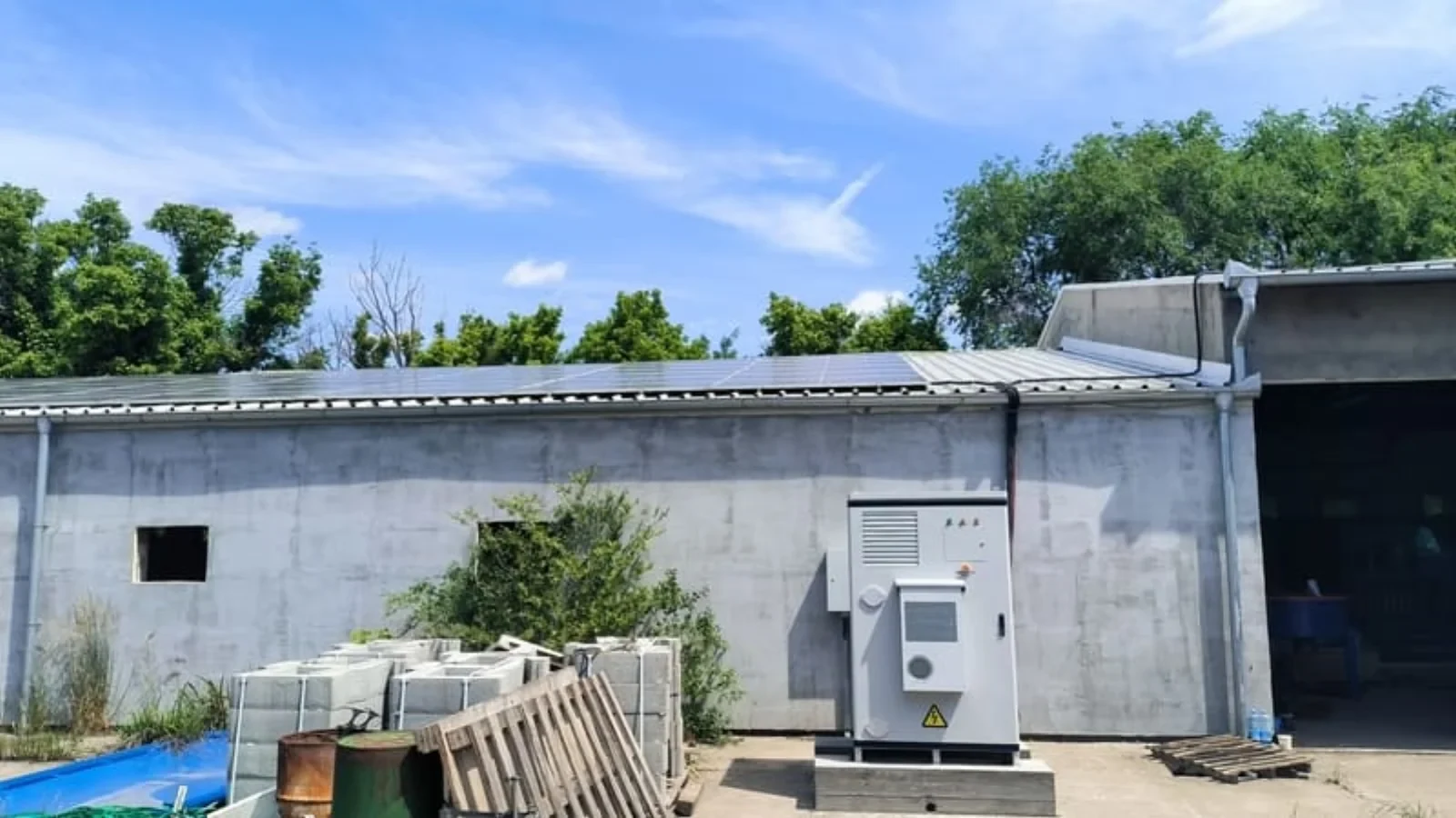
The existing side of a retrofit: the array and the wall-mounted unit stay, and the storage is designed around them.
Interface point | What it asks of the existing inverter | Where it fits |
|---|---|---|
AC bus, behind the meter | Nothing electrical; it keeps running as a grid-following unit | Residential and commercial, the common retrofit case |
DC bus inside the inverter | A spare battery input, a matching voltage window, a supported battery | Sites whose inverter is already hybrid or battery-ready |
Service entrance, front of meter | Separate metering, plant-level control, protection review | Commercial, industrial and utility-scale plants |
Whether you want the storage on the AC side or the DC side of an existing inverter is a genuine design decision with efficiency and cost consequences. That comparison — inverter losses, conversion stages, equipment counts — is covered in the AC-coupled versus DC-coupled retrofit comparison; this section addresses the connection point alone, as the first gate, because everything downstream depends on it.
Gate 2: Voltage and Power Windows
Compatibility language hides three separate measurements, and a project fails when any one of them is out of range. The efficient way to check is to collect the same fields for every device in the chain before anyone quotes hardware.
Field | Where it comes from | Gate it settles |
|---|---|---|
AC voltage and connection type (single-phase, split-phase, three-phase) | Nameplate and the site's supply | Gates 1 and 2 |
Rated and maximum AC power, maximum AC current | Nameplate | Gate 2 |
Export limit and any import cap set in the inverter | Inverter settings, and the interconnection agreement | Gates 2 and 4 |
DC input window and MPPT range, if the DC path is in play | Datasheet | Gate 2 |
Battery voltage window and maximum charge/discharge current | Battery datasheet and the inverter's supported list | Gates 2 and 3 |
Protection and metering arrangement at the coupling point | Single-line diagram and the site survey | Gates 1 and 5 |
The voltage half is easy to underestimate. Residential storage is split between low-voltage systems around 51.2 V and high-voltage stacked systems that run from roughly 173 V to 460 V; a battery in the wrong class does not become compatible through a cable. Behind both classes sits the same lithium-ion chemistry, so what changes between them is how many cells are strung in series, not what they are made of. If you are deciding which side of that line to land on, the trade-offs are set out in low-voltage versus high-voltage home batteries. Commercial equipment sits far above both, with battery strings in the 768 V to 1,331 V range depending on the platform.
The power half is where retrofit projects get into trouble with the utility rather than with the hardware. Storage on the AC side of the existing inverter is an added source on the same bus, and the connection limit that applies is the one in the interconnection agreement. A battery rated above the PV inverter's AC rating is often workable; a battery that pushes site export past the agreed limit is a paperwork problem before it is ever an engineering one, and in markets with a net-metering or export-tariff arrangement that limit is also the number that decides what the storage can earn. Rated power in kW and stored energy in kWh are also routinely confused in scoping conversations, which is what the battery sizing calculator exists to keep straight.
For the DC path, pair the voltage window with the vendor's approved battery list rather than with the logo on the datasheet. On that path, the document to ask for is a lithium battery compatible inverter list: the one that names which inverters the battery may be paired with, and without which there is no supported pair. That is the question meter-based control on the AC side never has to ask. Manufacturers maintain these lists because the pairing is a protocol relationship as much as an electrical one — Victron's public battery compatibility database is a good example of the document to demand: a named battery model, a voltage window and a supported interface, in writing.
Gate 3: The Control Interface
This is where retrofit compatibility differs most from new-build, and where the usual answer ("ask your installer") runs out. A new system has one owner for the energy decisions. A retrofit has three parties: the existing PV inverter, the new storage, and whatever is deciding when the battery charges. Somebody has to own that third role, and how you assign it is the gate that most often decides whether a site needs new hardware.
There are three workable levels, in descending order of how much the existing equipment has to cooperate.
Device-level closed loop. The battery's management system talks to the inverter over CAN or RS485, and the inverter owns charge and discharge within limits the battery publishes. This is the tightest arrangement and it requires a named, supported pairing — the battery and the inverter must appear on each other's lists. It is available if the existing inverter is a hybrid with a battery input, and unavailable on a plain grid-tie unit.
Site-level open protocol. The controller reads the existing inverter over an open interface — typically Modbus TCP, with the SunSpec register definitions as the interoperability layer; the SunSpec Modbus specification is one of the interfaces the IEEE 1547-2018 family of standards identifies for this kind of data exchange, alongside IEEE 2030.5 and IEEE 1815. Where the inverter exposes those registers and the vendor publishes a register map, a site controller can see production, limits and status, and can coordinate storage against them. Where the map is undocumented or locked to a firmware revision the owner cannot obtain, this level is closed.
Meter-based control. Current transformers or a revenue meter at the coupling point tell the storage what the site is importing or exporting, and the storage charges and discharges to follow that number. No protocol, no register map, no permission needed — it works with any inverter, including units from vendors that have left the market. The cost is depth: the system sees site-level flow, not device-level state, so it cannot act on inverter temperature, string faults or export limits that the inverter has already applied internally.
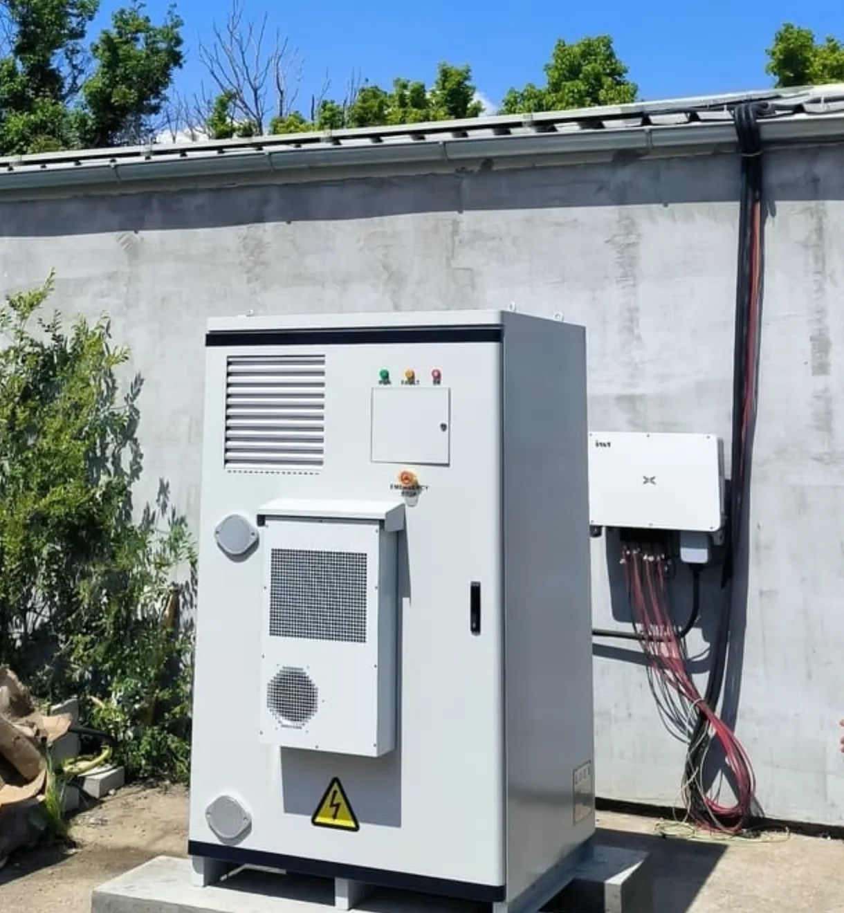
Two independent machines on one AC bus: this pairing is what makes meter-based control necessary, and what makes it sufficient.
Control level | What it needs | What you get | What you lose |
|---|---|---|---|
Device-level closed loop | A supported battery-to-inverter pairing | Charge control, limits, device data | Not available on plain grid-tie or microinverter systems |
Site-level open protocol | Modbus TCP plus a published register map | Production, limits and status from the existing inverter | Nothing, if the firmware and map are available |
Meter-based | CTs or a meter at the coupling point | Site import and export, and reliable control around them | Device-level state and fault data |
For a commercial site, the control layer is usually an energy management system rather than a single box, and the requirements for that layer — device onboarding, setpoints, what the controller can and cannot do across mixed vendors — are the subject of our EMS architecture whitepaper. The retrofit-specific rule is narrower and worth stating plainly: whatever cannot be read cannot be controlled, and whatever cannot be controlled has to be worked around with measurement.
Gate 4: Grid Code and Certification Version
Two different certificates decide this gate, and they are frequently confused.
The first belongs to the inverter that converts DC to AC, and it says which grid code revision the unit conforms to. In North America that is the UL 1741 family with the IEEE 1547-2018 requirements behind it; in Great Britain it is the G98 and G99 connection requirements, which the Energy Networks Association sets out for generators connecting to the distribution network; in the European Union it is the EN 50549 series and the national application rules. The second belongs to the storage itself, and it covers safety rather than grid behavior — for a battery system, the UL 9540 requirements for energy storage systems are the reference in North American projects, alongside the IEC 62619 and UN 38.3 documentation the cells and modules carry.
The retrofit detail that surprises people: adding storage to an existing connection point often triggers a fresh review of the equipment that is already there. A unit certified to an earlier revision of the same standard, or to a national variant that has since moved on, may need a settings or firmware update, an addendum, or replacement — and which of those three applies is decided by the network operator, not by the equipment owner.
Existing equipment status | Typical outcome |
|---|---|
Certified to the current revision, adjustable by settings file | Stays, with a documented settings update |
Certified to an earlier revision, vendor still supports updates | Firmware or settings update, if the operator accepts the path |
Certification the operator no longer accepts, or no vendor support | Replacement, with the array and the balance of system reused |
No verifiable certification documentation | Treated as the row above until proven otherwise |
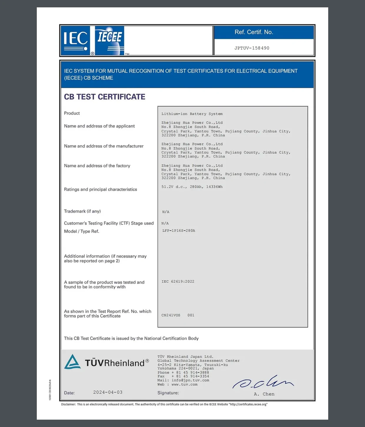
A certificate is a document, not a claim: on the storage side, safety conformity arrives as a test certificate with a reference number.
Rules here are set locally and revised on national timetables, so the practical sequence is to confirm the current requirement with the distribution network operator or utility before designing around the existing inverter, and to treat any general statement — including the ones in this article — as a starting point. Our guide to EU grid-connection compliance for storage covers the European process in more detail.
Gate 5: Backup and Islanding Topology
Backup is the gate that changes the physical design rather than the paperwork, and it is why some retrofits cost more than the storage alone suggests. There are three levels of ambition, and each adds equipment and constraints.
Backup level | What it adds | What it demands of the existing PV inverter |
|---|---|---|
No backup | Nothing beyond the storage and its controller | Nothing; the inverter keeps shutting down with the grid |
Critical-load backup | A transfer device and a backed-up sub-panel | It must accept a grid-forming source, and be able to limit its own output when the grid is absent |
Whole-site backup | Site-level transfer equipment and protection redesign | The same ability, at a scale where the array itself may exceed what the backup system can absorb |
The technical crux is the third column. During an outage the storage becomes the grid, and the existing PV inverter keeps trying to push power into it. Grid-tie inverters are built to stop in that situation, and a subset of them can be told to stay: the mechanism is frequency-watt droop control, in which the inverter throttles its output as the local AC frequency rises. Vendor documentation is explicit about the split. Tesla's published Powerwall compatibility table allows any inverter certified to UL 1741 to remain on the backup circuit but recommends units with frequency-watt droop control for island operation, and it caps third-party solar on the backup circuit at 7.68 kW AC per unit — a limit that many existing arrays exceed, which turns "keep the array running in backup" into a design decision rather than a checkbox.
Switching speed belongs in the same conversation. A transfer has to complete inside roughly one line cycle — 20 ms at 50 Hz, 17 ms at 60 Hz — or the loads it protects will notice. Integrated gear is documented in exactly those terms: the 125 kW AC-coupled cabinet in Hua Power's line quotes a 20 ms STS switchover, and equipment that is slower is not wrong so much as narrower in what the backup circuit can carry. The same Tesla table lists the units it recommends as alternative solar inverters — modern units with frequency-watt droop control that do not drive overvoltages during a fault, such as Enphase IQ8, SolarEdge HDWave and SMA Sunny Boy — a useful reminder that the recommendation follows the control feature, not the logo.
If the array cannot be throttled, the backup system has to be sized and switched so that the PV is disconnected or limited during island operation — which is a legitimate design, and one that is worth writing into the scope before installation rather than discovering during commissioning. Staging the work so the array keeps producing while the backup side is rebuilt is its own planning problem, covered in how fast a solar storage retrofit can be staged.
Gate 6: Lifecycle, Support and Reverse Compatibility
The final gate is the one nobody checks during procurement and everybody pays for later. Retrofitting and repowering of existing plants is not a niche event: an EPRI technical update on inverter retrofitting and repowering documents large plants that changed inverters for reasons including product life-cycle changes without reverse compatibility, original equipment manufacturers leaving the inverter business, weather damage, and better revenue opportunities — and it describes the case study in terms of mechanical, electrical and communications compatibility.
Read that list again, because every item on it is a normal business event rather than a failure. The lesson for a site adding storage today is to treat documentation as part of the equipment. Before signing, ask for: the approved-pairing statement covering your battery and inverter combination; the register map and the interface revision it applies to; a written statement on how long firmware and configuration support will continue; the warranty terms that mention third-party devices on the same bus; and who can service the unit if the original installer is not available. A procurement process that asks for these up front lines up with the checklist we use for commercial storage procurement, and it takes an afternoon.
There is also a monitoring question with a long tail. Production and consumption data collected from a retrofit usually lives in a vendor portal, and access to it outlives neither the warranty nor the vendor's interest in a discontinued product line. Confirm who owns and can export the data before the system is commissioned.
In an AC-coupled retrofit the battery does not have to agree with the inverter — because the two are not trying to talk to each other. Both work against the grid, and the grid does not care who is behind the meter.
What Works With What: Retrofits by Existing Inverter Class
The six gates resolve differently depending on what is already on the wall. This table is the short version — read the row that matches your existing equipment, then work the gate named in the last column first.
Existing inverter class | Viable interface point | What you add | What would force a replacement | Check first |
|---|---|---|---|---|
Microinverter array (one unit per panel) | AC bus, behind the meter | AC-coupled inverter and battery on the site's AC bus | A DC-coupled design; otherwise the array is untouched | Gate 1 |
Grid-tie string inverter, no battery input | AC bus, behind the meter | AC-coupled battery and inverter | Wanting DC coupling or a hybrid architecture on the existing unit | Gate 2 |
Hybrid or battery-ready inverter with a free battery input | DC bus inside the inverter | A battery on the vendor's supported list, inside the DC window | A battery outside the supported list or voltage window; a firmware path that no longer exists | Gate 2 |
Commercial multi-inverter or central plant | AC bus at the low-voltage board, or front of meter | PCS, battery, and plant-level control and metering | Plant-level control requirements the existing inverters cannot satisfy | Gate 3 |
Pre-2015 grid-tie unit, documentation available | AC bus, behind the meter | The same AC-coupled storage as any string array | A certification revision the unit cannot meet, and no update path | Gate 4 |
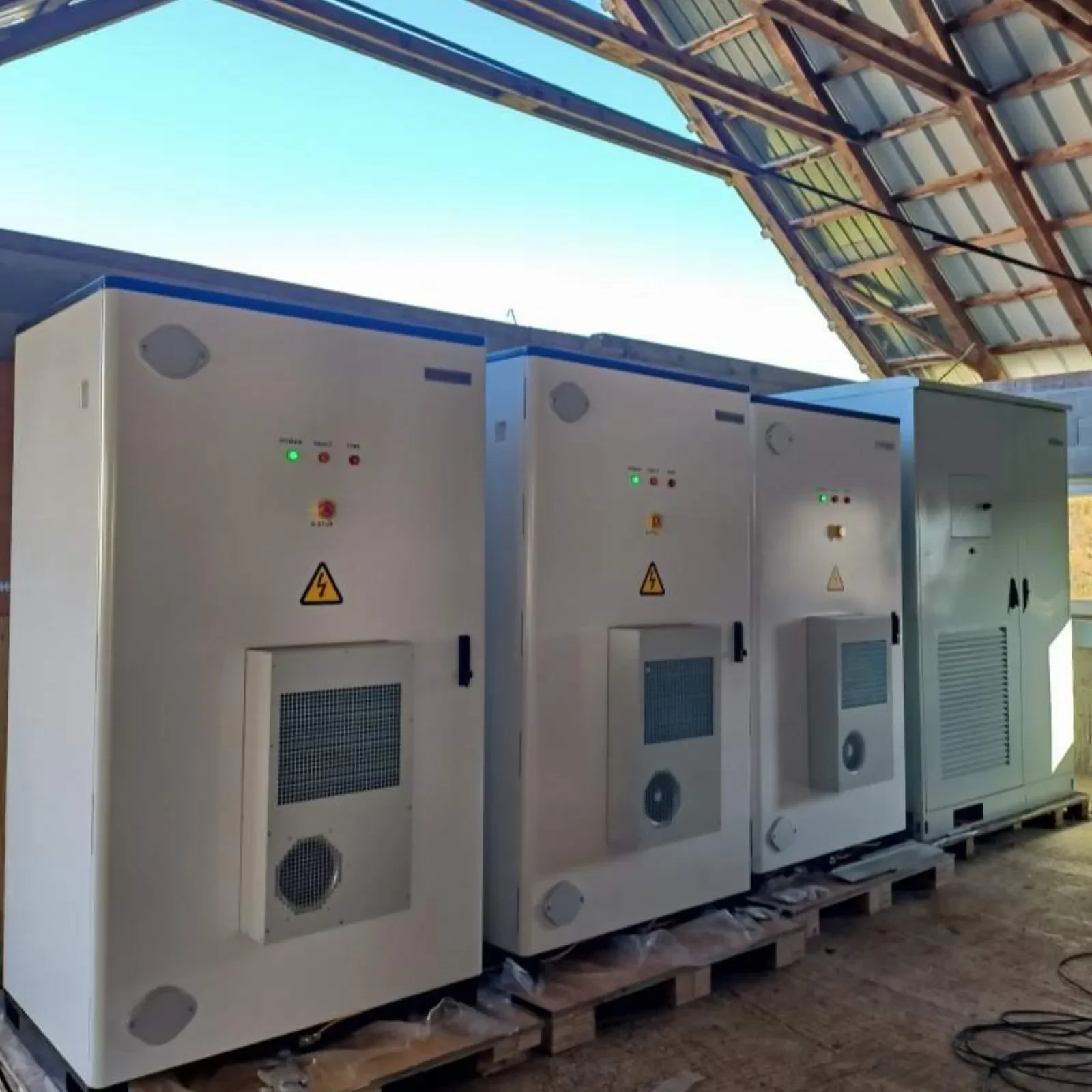
At commercial scale the connection point is usually a board or a meter position, not a device, and the cabinets arrive as a set.
The column headed What would force a replacement is not uniform, and the difference matters. Two of the five entries are a desire for a different architecture — DC coupling, or a hybrid where the unit is a plain grid-tie string inverter. One is a control requirement that older plants cannot satisfy. Two more, the firmware dead end in row 3 and the certification revision in row 5, are a support or certification problem rather than a design preference, and that pair is what turns a retrofit into a conversation with the network operator rather than a purchase order. Everything else is the practical meaning of AC-coupled retrofit compatibility.
Residential and Commercial Retrofits: Same Gates, Different Weight
The six gates apply at 10 kWh and at 1 MWh, but the order in which they break is nearly reversed, and that is worth knowing before you read a residential guide and apply it to a factory.
Residential, single-phase | Commercial and industrial, three-phase | |
|---|---|---|
Typical storage range | 5 kWh to about 50 kWh; 51.2 V low-voltage or 173-460 V stacked | 100 kWh to several MWh; battery strings from 768 V to 1,331 V |
Gate that breaks first | Gate 2, then Gate 5: windows and backup sizing | Gate 3, then Gate 4: control ownership and certification revision |
Where the storage connects | Behind the meter, on the consumer unit or a backed-up sub-panel | Behind the meter at the low-voltage board, or front of meter with its own metering |
Backup expectation | Whole-home or critical loads, with PV often outside the backup circuit | Sectional or plant-level, with protection and transfer designed as a system |
Who signs off | The installing contractor and the utility connection | The network operator, plus a plant-level control and protection review |
For an AC-side retrofit on a commercial site, the storage arrives as an AC-coupled battery storage inverter in its own cabinet, with no PV input at all: the conversion equipment is sized against the plant's load and connection limit rather than against the array, which is the same selection problem that choosing a commercial battery inverter works through. That is the configuration the HC-UPSA241 takes — 241.152 kWh of battery, no PV input — for a site where the array stays exactly as it is and the bus alone gets a new participant. Battery containers go further in the same direction, shipping without a conversion system so a plant can keep the conversion equipment and the interconnection it already has. If you already own the array and want to know which of these configurations survives your six gates, that is the conversation to have before a purchase order rather than after — talk to our engineers about a site review.
The Pre-Design Checklist: What to Collect Before You Commit
Nothing in this article is exotic, and almost all of it is decided by documents that already exist. Collect these twelve things before hardware is specified:
Item | Where to get it | Gate |
|---|---|---|
Inverter model, firmware revision and nameplate ratings | The unit itself, not the installer's memory | Gate 2 |
Grounding and neutral arrangement at the coupling point | Site survey, and the wiring rules that apply locally | Gate 1 |
Battery voltage window, current limits and approved-pairing list | Battery vendor, in writing | Gates 2 and 3 |
Register map and interface revision for the existing inverter | Inverter vendor's technical support | Gate 3 |
Metering or CT position, and what the storage can measure there | Site survey and single-line diagram | Gate 3 |
Interconnection agreement or connection offer, with the export limit | Network operator or utility | Gates 2 and 4 |
Certification revision of the existing inverter, and the revision the operator requires | Vendor declaration, plus the network operator | Gate 4 |
Single-line diagram with the coupling point marked | Installer or facility documentation | Gates 1 and 5 |
Panel and protection ratings at the coupling point, and the spare ways available | Site survey | Gates 1 and 5 |
Backup scope in plain words: nothing, critical loads, or the whole site | The site owner | Gate 5 |
Array AC rating, if PV is expected to run during an outage | PV system documentation | Gate 5 |
Warranty terms on both sides that mention third-party equipment | Both vendors | Gate 6 |
Five ways these projects stall, in rough order of frequency: a battery in the wrong voltage class discovered after delivery; a certification revision nobody checked until the operator asked; a backup circuit sized for the array rather than for the load; a control layer that needed a register map the manufacturer would not release; and monitoring data the owner cannot export when they later want to switch platforms.
Every one of those is a first-week question rather than a commissioning-week discovery. Start with the nameplate and the interconnection document, work the six gates in order, and the retrofit decision usually resolves in an afternoon — often with the existing inverter still on the wall.
Quick Answers
What is inverter compatibility in a retrofit? It is whether the equipment already on site can take part in a storage system without being replaced. Six checks decide it: connection point, voltage and power windows, control interface, grid-code revision, backup topology and lifecycle support. Brand pairing is a different question.
Do I have to replace my existing inverter to add a battery? Usually not, when the storage couples on the AC side. Replacement comes into the picture when you want DC coupling on a unit with no battery input, when the unit's certification revision is no longer accepted at the connection point, or when there is no firmware path left to configure it.
What does AC-coupled mean for a retrofit? The storage brings its own inverter and ties to the same AC bus as the existing PV inverter. The two run independently, so neither machine has to understand the other.
What most often blocks a retrofit? Voltage classes that surface late, certification revisions that went unchecked, backup circuits sized around the array, and control layers that depend on a register map the manufacturer will not release. The pattern behind all four is the same: the constraint was documented somewhere before anyone bought anything.
This article is engineering background rather than design advice for a specific site. Work on a PV system's electrical installation has to be carried out by licensed personnel under the local code, and the connection requirements that apply are the ones set by the network operator or utility serving the site — confirm them before committing equipment.