

What an AC-Coupled Energy Storage Cabinet Actually Is
An AC-coupled energy storage cabinet is a self-contained battery enclosure with its own bidirectional AC inverter (PCS). It connects to a site's low-voltage AC bus — alongside an existing PV inverter's AC output — rather than onto a shared DC bus. It can charge and discharge without rewiring the solar array's DC circuits.
The load-bearing word in that sentence is cabinet. Three different products get called "AC-coupled storage", and they solve different problems. A home battery is a single-phase appliance sized in single-digit kWh for one building. A containerised system is a multi-megawatt project — a container BESS starts around 2 MWh and runs past 5 MWh as an ISO-footprint unit. A cabinet sits between them: one pad-mounted enclosure of about 2.5 tonnes, 1600 × 1103 × 2254 mm on the HC-UPSA241, feeding a three-phase 400 V bus at 105 kW.
Same coupling principle, completely different electrical envelope — and on a retrofit project, the envelope is what decides whether the numbers work. An AC coupled energy storage cabinet of this class is specified from its AC interface inward: the bus it connects to, the power it can move, and the energy it can actually release.
AC-coupled does not mean "PV required". The coupling describes where the battery connects, not what charges it. A cabinet on an AC bus can take energy from a PV inverter, from the grid at off-peak rates, or from both, and it can still support an islanded load if the design includes the right transfer equipment.
AC coupling is not a downgrade of DC coupling. The two architectures differ in where conversion happens. DC-coupled designs put PV and battery behind one hybrid inverter and can capture energy that an AC-side limit would otherwise block. If that trade-off is the question in front of you, the AC coupling fundamentals entry covers the electrical basics, and the architectural comparison lives in AC vs DC coupled solar retrofit. This article stays on the cabinet side: what a 105 kW class unit is, what its numbers constrain, and how to verify one before you buy.
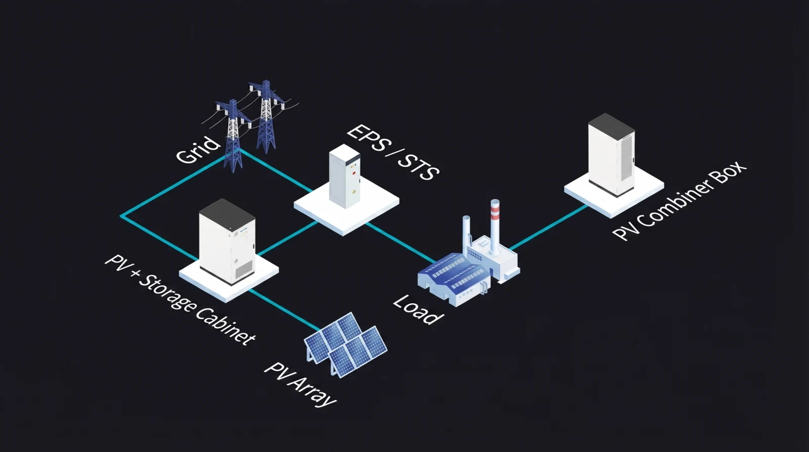
Where an AC-coupled cabinet lands on a live site: the array and combiner box feed the PV + storage cabinet, which sits behind an EPS/STS transfer point between the grid and the load.
Why Retrofit Projects End Up on the AC Side
A retrofit rarely starts with a technology preference. It starts with an asset that works.
Most commercial PV plants built in the last decade are still producing, and their string inverters are still supported. Replacing that equipment to add storage turns a storage project into a re-powering project: new inverters, new string design, new DC protection settings, re-commissioning, and PV production offline. An AC-coupled cabinet avoids that scope: AC coupled battery storage connects on the AC side of the existing inverter, so the array's DC circuits stay untouched and the battery gets its own protection and metering.
That is the trade. You accept one extra conversion step — PV energy that charges the battery crosses DC→AC at the PV inverter and AC→DC at the cabinet — in exchange for leaving a working array alone. Its cost depends on the equipment and the operating point, so model it from the two datasheets rather than a rule of thumb. The HC-UPSA241's datasheet lists a maximum efficiency of ≥85%; ask any supplier to define that boundary (inverter stage or full AC-to-AC round trip, and at what load fraction) before it enters a savings model.
A second constraint gets missed: with an AC-coupled design, the energy available to charge the battery is what the PV inverter delivers to the AC bus, minus what the building consumes. If the interconnection agreement caps export, or the inverter uses a zero-export setting, that cap also caps charging. A DC-coupled design can sometimes absorb PV that the AC side cannot accept, so on a site whose array is oversized relative to load, model that difference before committing to either side.
So the retrofit logic is straightforward. Keep the AC side when the existing PV inverter is healthy, when the site already has a three-phase 400 V distribution point with a spare way, and when disruption to the array is the main project risk. Look hard at re-powering instead when the inverter is near end of life, or when the array's surplus is large enough that reclaiming clipped energy would change the business case. The U.S. Department of Energy's energy storage overview is a neutral primer on how storage value is framed. The cluster hub on solar retrofit battery storage covers the wider retrofit sequence; what follows here is the cabinet itself.
Inside the HC-UPSA241: The Numbers That Decide a Project
Hua Power's HC-UPSA241 AC coupled storage is a 105 kW / 241.152 kWh air-cooled cabinet built for exactly the scenario above. Rather than transcribe the datasheet, read the numbers the way a project engineer has to: what does each one constrain?
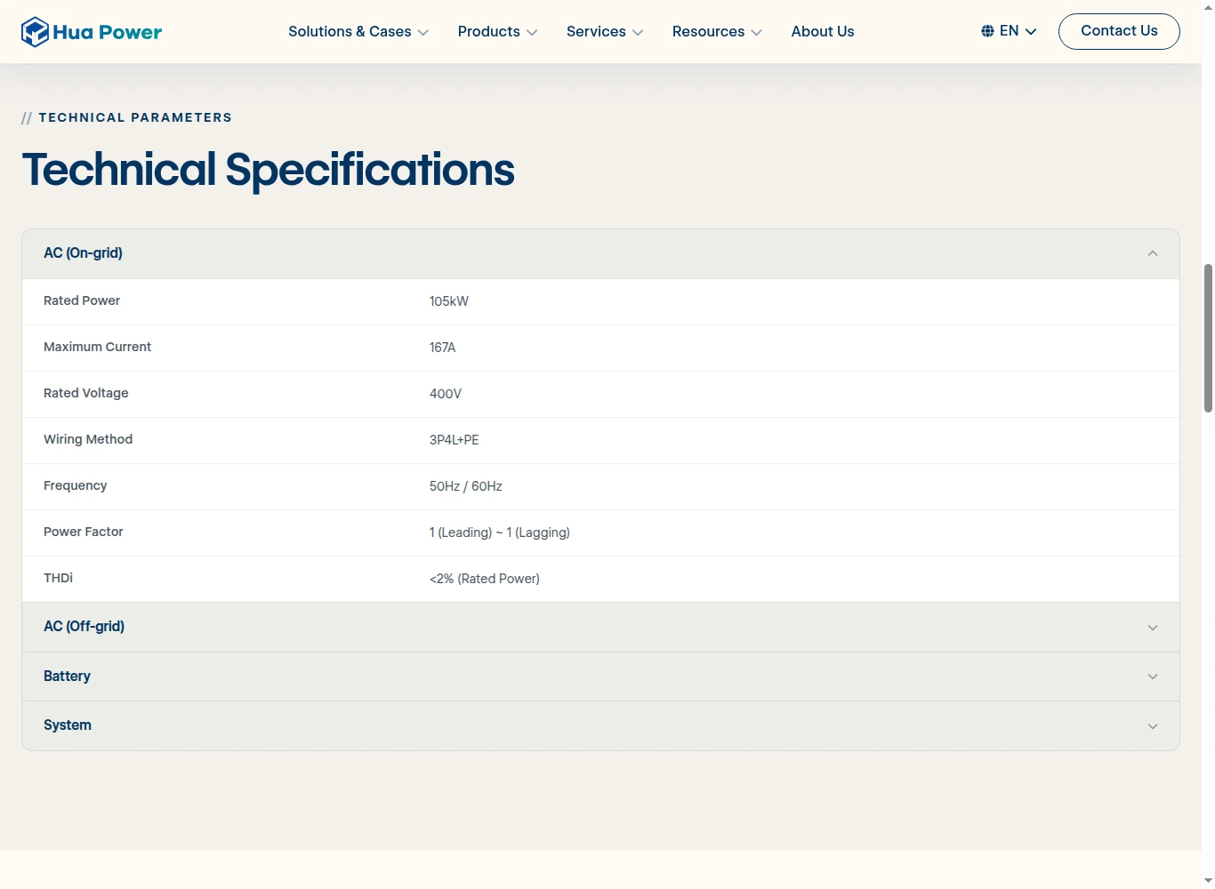
The published AC interface figures for the HC-UPSA241: 105 kW rated power, 167 A maximum current, 400 V, 3P4L+PE wiring, 50 Hz / 60 Hz, and THDi below 2% at rated power.
Specification | HC-UPSA241 value | What it constrains in a project |
|---|---|---|
Rated AC power | 105 kW (on-grid and off-grid) | The peak the cabinet can shave or carry on backup. It is also the binding number for discharge duration. |
Rated AC voltage and wiring | 400 V, 3P4L+PE, 167 A maximum current | Whether your low-voltage board has a spare three-phase way, cable and breaker rating, and transformer headroom. |
Battery capacity | 241.152 kWh, LiFePO4, 648–864 V, 15 packs per cluster | How much energy one cabinet stores. Nameplate, not usable — see the next section. |
Charge / discharge rate | 0.5 CP, 90% depth of discharge | How hard the cells are worked. It sets whether the cabinet can shift a full charge inside a short tariff window. |
Power quality | THDi <2% at rated power, THDu <3% on linear loads | Interaction with the site's existing harmonics and the limits your utility applies to them. |
Thermal and site ratings | Air cooling, IP54, C4 anti-corrosion, −20 °C to 50 °C with derating above 45 °C, altitude to 2000 m, ≤75 dB | Where the cabinet can physically sit, and what its output becomes on a hot afternoon or at altitude. |
Safety and market access | FK-5-1-12 fire protection, CE, UN 38.3 | What documentation you can hand to an insurer, an authority, or a customs broker. |
Two rows deserve more than a table cell. The AC interface is where most first-pass designs fail: 167 A needs a properly rated way in the distribution board, and the transformer upstream has to have room for the existing PV inverter and the new load. The temperature row is where a hot-climate project quietly loses capacity — derating starts above 45 °C ambient, so a cabinet rated 105 kW in a temperate climate is a different machine at 48 °C.
The full AC, battery and system tables — plus the datasheet and certificate list — are on the HC-UPSA241 product page.
The Math Most Buyers Get Wrong: Nameplate vs Usable Energy
Buyers routinely put a cabinet's nameplate capacity into a financial model as though the site could use all of it. It cannot, and the gap moves payback calculations.
The
HC-UPSA241 stores 241.152 kWh at the battery level. Its declared depth of discharge is 90%, which puts roughly 217 kWh at the cabinet boundary before conversion losses and the cabinet's own auxiliary consumption. Then the power limit takes over: at a rated 105 kW, 217 kWh lasts about 2.07 hours, not the 2.30 hours the nameplate implies.
Working figure | Value | How it is derived |
|---|---|---|
Nameplate battery capacity | 241.152 kWh | Datasheet value |
Usable energy at 90% depth of discharge | ≈217 kWh | 241.152 × 0.90 |
Discharge duration at 105 kW | ≈2.1 hours | 217 ÷ 105 |
Battery charge / discharge rate | 0.5 CP ≈ 120.6 kW | Datasheet rate applied to nameplate capacity |
Auxiliary load | 3 kW cooling, 2.5 kW heating | Datasheet value |
Two conclusions fall out of that table. First, the cabinet's 105 kW AC rating — not its battery rate — caps discharge power: the cells are rated at roughly 120.6 kW, so the PCS is the limiting component, and more battery capacity alone will not raise the site's peak-shaving ceiling. Second, the auxiliary load is real: 3 kW of cooling for a 2.1-hour discharge consumes about 6 kWh, close to 3% of usable energy, and more on a high-ambient outdoor pad. Modelling round-trip performance from datasheet capacity alone overstates what the meter will see.
The number to put in the model: around 217 kWh usable, not the 241.152 kWh printed on the nameplate — and at a rated 105 kW that is a little over two hours of discharge, before auxiliary loads and conversion losses are deducted.
One number is a five-year question rather than a two-hour one: cycle life is declared at ≥6000 cycles to 80% state of health under standard conditions. Ask for the conditions, not the headline — temperature, depth of discharge, charge rate and the end-of-life definition all move that number, and they decide whether a warranty claim holds in year six.
Eight Checks Before You Sign Off on an AC-Coupled Cabinet
Specifications answer "what is it". These eight checks answer "will it work on my site" — the questions worth taking into a design review or RFQ.
1. The AC interface and its protection. Confirm the bus configuration (three-phase four-wire plus earth on the HC-UPSA241), the maximum current the cabinet can draw and deliver (167 A), and that the distribution board has a correctly rated way, breaker and cable. Then check transformer headroom against the existing PV inverter plus the new cabinet.
2. Grid code and interface settings. The cabinet is declared at 50 Hz / 60 Hz with a power factor range of 1 leading to 1 lagging. Ask who owns the interconnection settings, what the local grid code requires for a storage system of this size, and whether an interconnection study is triggered. In the United States, system-level safety evaluation typically runs through the UL 9540 listing, built on test data from components evaluated under UL 1973.
3. Power quality, measured against your site rather than the datasheet. Total harmonic current distortion below 2% at rated power is a good figure, but it describes the cabinet, not the bus. IEEE's standard for harmonic control in electric power systems is where the limits that utilities apply come from. If your site already runs distorting loads, ask for the combined picture at the point of common coupling.
4. Export control and operating limits. Establish what happens when the battery is full and the array is still producing, and how the control system enforces an export cap or a zero-export setting. This is the single most common source of post-commissioning disputes on retrofit sites, because it is a controls agreement, not an equipment rating.
5. Backup and islanding design. The HC-UPSA241 is specified for off-grid operation at the same 105 kW and 400 V, with harmonic distortion below 3% on linear loads. That rating is the starting point for backup, not the design. Decide which loads are backed up, how the site transfers between grid and island, and whether the existing PV inverter can run against a grid-forming source while islanded. On retrofit battery storage projects, this transfer scheme is usually the part that needs a specialist, not the cabinet.
6. Thermal behaviour, siting and noise. Derating above 45 °C ambient, altitude derating above 2000 m, IP54 enclosure and C4 anti-corrosion are all siting inputs. So is the 75 dB(A) noise ceiling, which matters when the pad sits near an office wall or a property line. Installation spacing and fire protection come from the locally adopted fire code — in the US, the NFPA 855 standard for stationary energy storage installation is where most jurisdictions start.
7. Safety documentation, not safety adjectives. FK-5-1-12 fire suppression, thermal warning algorithms and explosion venting are the layers named on the HC-UPSA241 datasheet. Turn each into a document request: the certificate index, the UN 38.3 transport test summary, and — where the jurisdiction requires it — the UL 9540A test report behind any fire-propagation claim. UL 9540A is a test method that produces data; UL 9540 is a listing for a complete system, and a component certificate is not a system approval. For European projects, the CE marking process is what turns a declaration into market access.
8. Monitoring, service and handover. The HC-UPSA241 communicates over Ethernet and supports remote diagnostics and firmware updates. Agree what data reaches whom, how often, and who may change control parameters. With a 2.5-tonne enclosure, settle the lifting plan, pad tolerances and service access before delivery day — access problems are cheaper to design out than to crane around.
Sizing One Cabinet Against Your Load Profile
Two failure modes show up again and again in first-pass cabinet sizing. Sizing on energy alone gives you a battery that empties before the peak period ends. Sizing on power alone gives you a number that looks right on a one-line diagram and does nothing for the bill.
Rule of thumb: on an ac coupled energy storage cabinet of this class, size the power first — how many kilowatts come off the peak — and the energy second, from how long that peak lasts. A commercial battery storage cabinet with adequate kW and too little kWh will disappoint at month end, and the reverse is harder still to explain to a finance team.
Start with 15-minute interval data — utility meter data, not monthly totals — and separate two questions. How many kilowatts must come off the peak, and how long does that peak persist? A 150 kW peak spread over two hours asks for something different from the same peak spread over 20 minutes.
A worked case: a two-hour peak window. One HC-UPSA241 discharges at up to 105 kW for about 2.1 hours, covering the window with margin. The resulting site peak depends on the rest of the load, so simulate it interval by interval rather than assuming it. Then check the recharge side — if the night-time tariff window is shorter than 2.3 hours, the 0.5 CP battery rate and the 105 kW AC limit both have to be checked against it, and the shorter of the two governs.
Vendor application notes for this cabinet state a 30–50% reduction in peak demand charges through tariff-aligned scheduling. Treat that as a vendor claim and model it against your own tariff, load shape and peak definition — the utility's ratchet clause usually decides the outcome. The method is set out in commercial peak shaving with energy storage.
When one cabinet is not enough, capacity scales by paralleling units: the air-cooled family runs from 105 kW / 241.152 kWh to 500 kW / 1,205.76 kWh, and the wider energy storage cabinet range shows how the form factor scales before a project moves to containers.
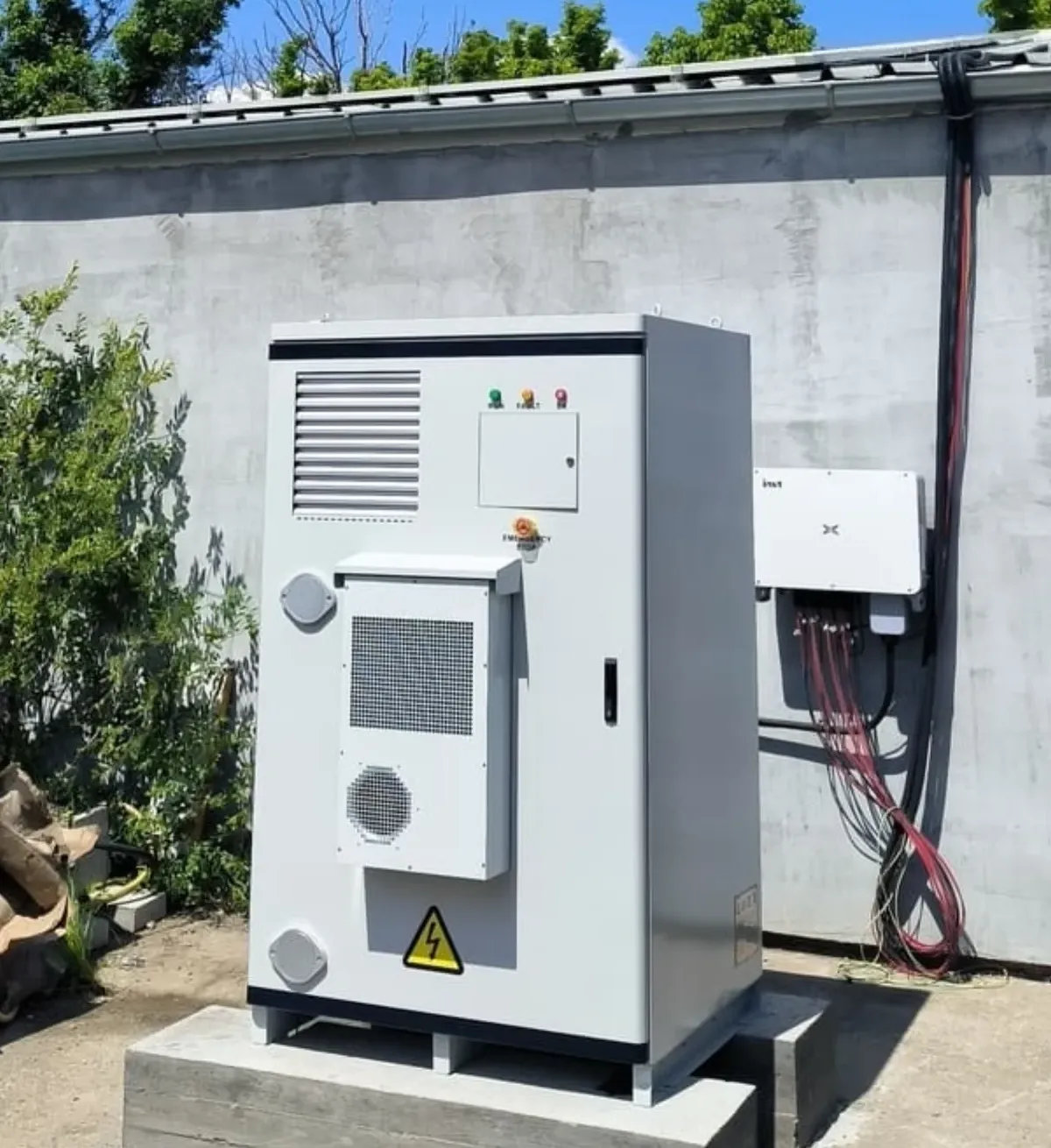
A deployed cabinet on a concrete pad, with existing wall-mounted conversion and distribution equipment alongside — the typical physical setting for a retrofit where the AC side stays as it is.
Where the HC-UPSA241
Fits — and When It Doesn't
Honest fit assessment saves more project time than any feature list. Whether an AC-coupled battery storage cabinet is the right answer depends on a specific shape of project, and the HC-UPSA241 suits that shape closely.
Project signal | Why a 105 kW cabinet fits | What to verify first |
|---|---|---|
Working three-phase PV plant, inverter still supported | Keeps the array and its DC design untouched | AC bus spare capacity and transformer headroom |
Peak demand of roughly 150–300 kW with a 2–3 hour peak window | One cabinet's 105 kW and ~217 kWh usable match that shape | Interval data and the utility's peak definition |
Critical loads needing backup during outages | Off-grid mode is specified at the same 105 kW, 400 V | Transfer scheme, backed-up loads, inverter behaviour while islanded |
Outdoor pad, temperate to hot climate | IP54 and C4 anti-corrosion enclosure, air cooling | Ambient derating above 45 °C, clearance and noise distance |
The table reads in reverse when the fit is wrong. A single-phase domestic service is not a cabinet project; a multi-megawatt, four-hour utility requirement belongs in containers. A pad with no spare room, or a noise-sensitive boundary metres away, needs a different siting answer before a different product. And a site whose PV inverter is already due for replacement should evaluate re-powering with DC coupling first, because the constraint that justifies AC coupling has already gone.
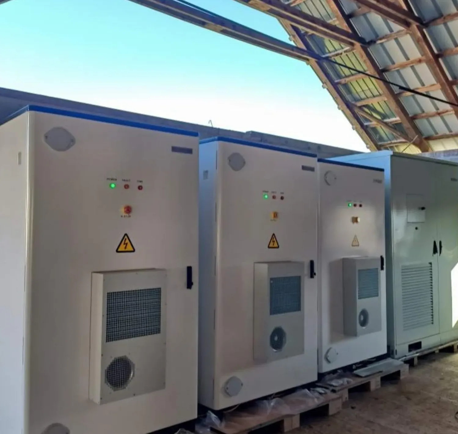
Three cabinets of this class staged before installation. Footprint, lifting weight and service clearance are set by the enclosure, not by the battery capacity inside it.
What to Collect Before You Ask for a Quote
A supplier can size a cabinet against the information you hand over. Collect these six items first, and the first proposal you receive will be one you can actually evaluate:
What to collect | Why the design depends on it |
|---|---|
AC bus details | Voltage, configuration, spare ways and transformer rating decide whether the cabinet connects at all. |
15-minute interval data, 12 months | Load and PV shape set both the peak to shave and the energy needed per event. |
The peak window and the utility's peak definition | Includes any ratchet clause — that clause usually decides the value of the project. |
Backup requirements | Which loads, for how long, and how the site transfers between grid and island. |
Site constraints | Pad dimensions, ambient temperature range, altitude, noise distance and corrosion environment. |
Existing PV inverter model and firmware | Determines whether the AC-side constraint still holds, and what the interconnection agreement allows. |
With those six, the discussion moves from product features to project fit — and the right cabinet size usually falls out of the data, not a brochure. If schedule is the constraint rather than equipment, the 7-day solar storage retrofit plan in this cluster sequences the same work against a timeline.
If you would rather hand the information over and get a configuration back, send your site requirements to Hua Power's engineering team and they will return a system configuration and commercial proposal for the site in question.