

Most mismatched pairs of high-voltage batteries and hybrid inverters are not caught at the quotation stage. They are caught on site: the inverter refuses to charge because the battery's BMS is not on its protocol list, or it sits at half power because the battery's operating window pokes outside the inverter's DC input range. The words "high voltage" on both datasheets tell you almost nothing about whether the two will work together.
A high voltage battery hybrid inverter pairing is an interface problem, not a brand problem. There are five interfaces, and they resolve best in a fixed order: the DC voltage window, the BMS communication protocol, the current limits on both sides, the phase count and AC topology, and the certification scope of the assembled system. Work them out of order and you end up with two products that are individually correct and jointly unusable.
This guide runs the five checks in the order that produces the fastest no — which is the answer you want before a deposit moves.
What a High-Voltage Battery Hybrid Inverter Pairing Actually Has to Match
The five interfaces look harmless on paper because each one lives in a different document. The voltage window is in the battery specification. The protocol list is in the inverter manual, if it exists at all. The current limits are split across both. The phase count is a site condition. Certification is a regulatory layer that sits above the hardware.
Compatibility, in other words, is not a property of either product. It is a property of the pair, and it only exists when all five interfaces agree.
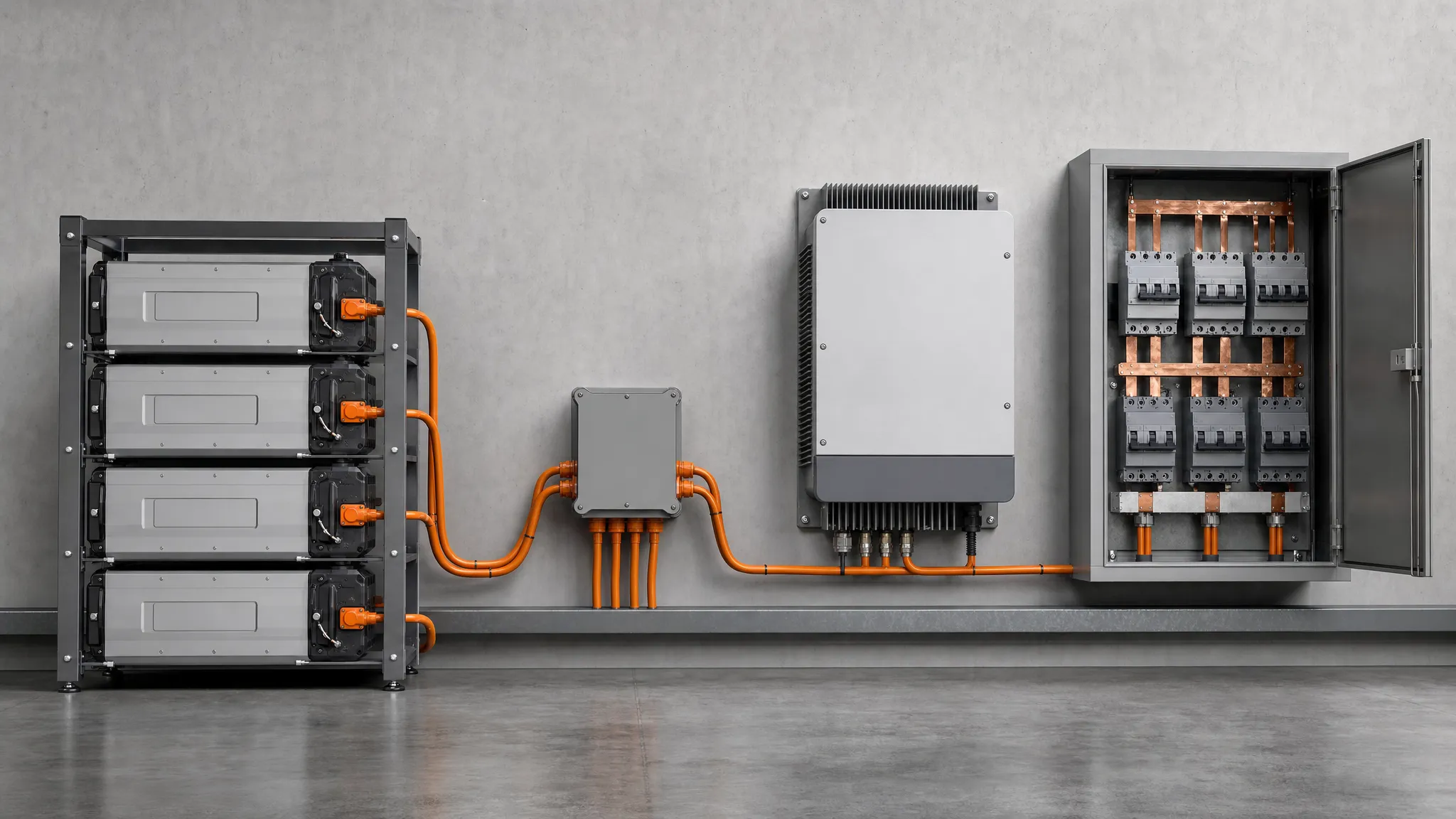
The battery stack, BMS, hybrid inverter and AC distribution side of a high-voltage pairing.
Step 1 — Match the Voltage Window Before You Look at Capacity
The battery's DC operating range has to sit inside the inverter's battery input range — both ends of it. A stack that swings from 172.8 V when empty to 230.4 V when full will not work with an inverter whose battery port only accepts 200 V and above, no matter how well the kWh figures line up.
Two numbers from real datasheets show how wide the gap between products can be. The LTN-25/30/40/50KHV-3PH three-phase hybrid inverter accepts a battery voltage range of 160–800 V and gives you two battery inputs. A vendor whose inverter only takes 200–500 V would reject a large share of the stacks in the table below.
The same numbers expose a second trap. That inverter's PV string input has a separate window — maximum DC input 1000 V and MPPT range 150–850 V. Buyers routinely read the PV window and assume it describes the battery port. It does not. On any high voltage battery inverter datasheet, the two are independent inputs with independent limits, and the first number to circle is the one labelled for the battery.
Battery stack (nominal platform) | Operating window | Fits a 160–800 V battery input? | Fits a 200–500 V battery input? |
|---|---|---|---|
20 kWh class, ~200 V platform | 172.8–230.4 V | Yes | No — low end sits below 200 V |
30 kWh class, ~300 V platform | 259.2–345.6 V | Yes | Yes |
40 kWh class, ~400 V platform | 345.6–460.8 V | Yes | Yes |
241 kWh cabinet, 768 V platform | 672–840 V | No — upper end exceeds 800 V | No |
The stacks in the first three rows are the published residential ones — for example the HC-UPSSHV20I / 30I / 40I high-voltage stackable series at 20.48, 30.72 and 40.96 kWh, whose published HC-UPSSHV20I specification lists those operating ranges. The fourth row is a commercial cabinet, included because a higher platform voltage is not automatically a better fit: its 672–840 V window overshoots both a 160–800 V and a 200–500 V battery input.
Capacity alone is a poor proxy for anything here. Two 20 kWh high voltage home batteries can sit on a 200 V platform or a 400 V one, and that single difference changes the current, the cabling and the inverter class you need. The voltage architecture matters more than the kWh figure, which is why high-voltage and low-voltage home batteries end up with such different balance-of-system costs.
Step 2 — Settle the BMS Communication Protocol Before You Order
In a high voltage battery hybrid inverter pairing, this is the check most buyers skip, and it is the one that produces the most expensive surprises.
A high-voltage stack has a battery management system that measures cell voltages, temperatures and state of charge, and enforces the charge and discharge limits. How the inverter learns those limits decides whether the pair behaves.
- Closed-loop communication — the BMS publishes limits over a digital link (CAN is the usual one on residential and commercial equipment), and the inverter follows them in real time. The battery stays in control of its own safety envelope.
- Open-loop operation — the inverter has no live data from the BMS and falls back on voltage thresholds you configure. Nothing is broken, but the inverter is guessing at what the battery will accept, and the safety layer sits in the wrong place.
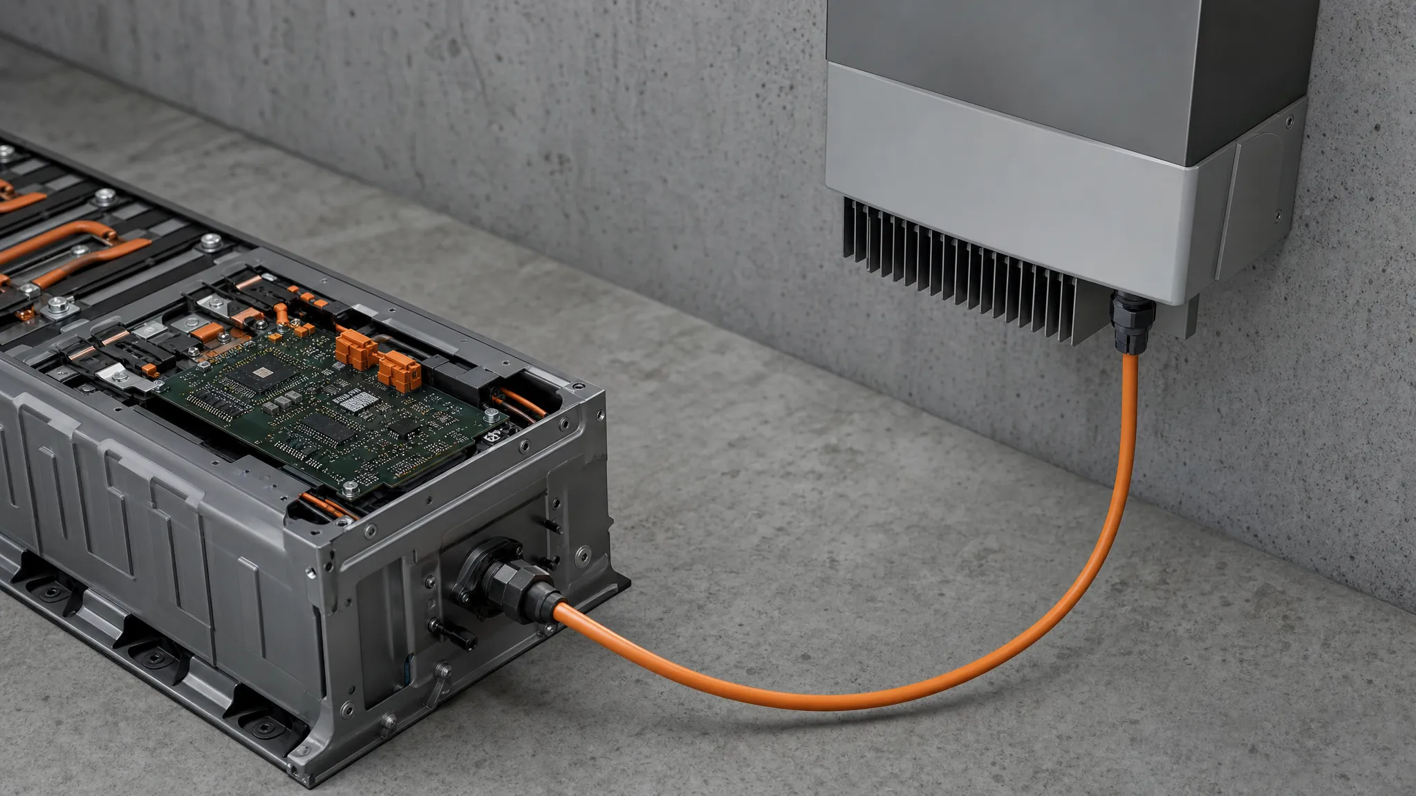
Closed-loop pairing puts the battery's BMS in charge of the charge and discharge envelope; open-loop leaves the inverter guessing.
Before ordering, ask for four things in writing:
- The protocol name and version the battery's BMS speaks, and the physical layer it uses (CAN, RS485, or both).
- Written confirmation from the inverter manufacturer that this battery model is supported, naming the firmware version. The inverter side owns this list; a battery vendor cannot certify someone else's firmware.
- The maximum number of battery inputs, and how the inverter aggregates limits across parallel stacks.
- What happens on a protocol timeout — does the inverter shut the battery port down, or fall back to open-loop thresholds?
Point two is the one that decides most projects, and it is also why certification bodies treat communication as part of the system rather than a feature. Under UL Solutions' certification pathway for DC energy storage systems, a DC block paired with an approved subsystem is evaluated for its "electrical, communication and interoperability" with that subsystem. The handshake is on the certification record, not just in the commissioning checklist.
Step 3 — Check Current Limits, Not Just Voltage
Voltage decides whether the pair can connect. Current decides how much power actually moves.
Both sides publish a number, and the smaller one caps the system. A six-kilowatt hybrid inverter pulling 6 kW from a stack sitting at 230.4 V is drawing about 26 A. A 125 kW commercial unit running at 768 V draws around 163 A for the same percentage of load. On the battery side, the manufacturer's specification sheet for the HC-UPSSHV series above lists 50 A rated and 100 A maximum charge and discharge current.
Example pairing | Voltage at the battery port | Current for the target power |
|---|---|---|
6 kW residential hybrid inverter | 230.4 V | ≈ 26 A |
22.8 kW output, 400 V battery platform | 400 V | ≈ 57 A |
22.8 kW output, 51.2 V battery platform | 51.2 V | ≈ 445 A |
125 kW commercial unit | 768 V | ≈ 163 A |
The third row is the reason this section exists. Moving 22.8 kW at a 400 V platform takes roughly 57 A; the same 22.8 kW at a 51.2 V low-voltage platform takes about 445 A. Same power, eight times the current, and current is what you buy cable, breakers and terminations for.
The rule to carry into the worksheet: the pair is capped by whichever current limit is lower, and by what the battery can still deliver at the bottom of its voltage window — not at nominal voltage.
One more effect catches people out: available power shifts as the stack moves through its window. A 40 kWh stack at 50 A delivers about 23 kW at 460.8 V, the top of its window, and about 17.3 kW at 345.6 V, the bottom. A 20 kW backup load passes at full charge and fails as the stack empties, so check the power available at the lowest operating voltage, not nominal.
C-rate gives you the sanity check. 50 A on a 100 Ah stack is a 0.5C charge or discharge. If the inverter wants to charge at a higher rate than the battery's published maximum, the battery wins and the inverter throttles — plan for the throttled figure rather than discovering it. The trade-offs between 0.25C, 0.5C and 1C designs are covered in this guide to C-rate selection for storage.
One number worth requesting alongside the current limits is the round-trip efficiency of the pair. The system figure is a product of the battery's own efficiency and the conversion stage's, so it can only be confirmed once the two are matched — a pair with a fast charge rate and a poor conversion stage can lose more on every cycle than it gains on the cable.
Step 4 — Match the Phase Count and the AC Side
The DC side of a battery-inverter pair is phase-agnostic. The AC side is not.
A single-phase high voltage hybrid inverter serves a 230 V residential service and typically lands in the 5–10 kW class. A three-phase high voltage hybrid inverter serves a 400 V service and starts in the 10 kW class, with the LTN models in the 25–50 kW band. Picking the wrong one is not a firmware problem; it is a reinstall.
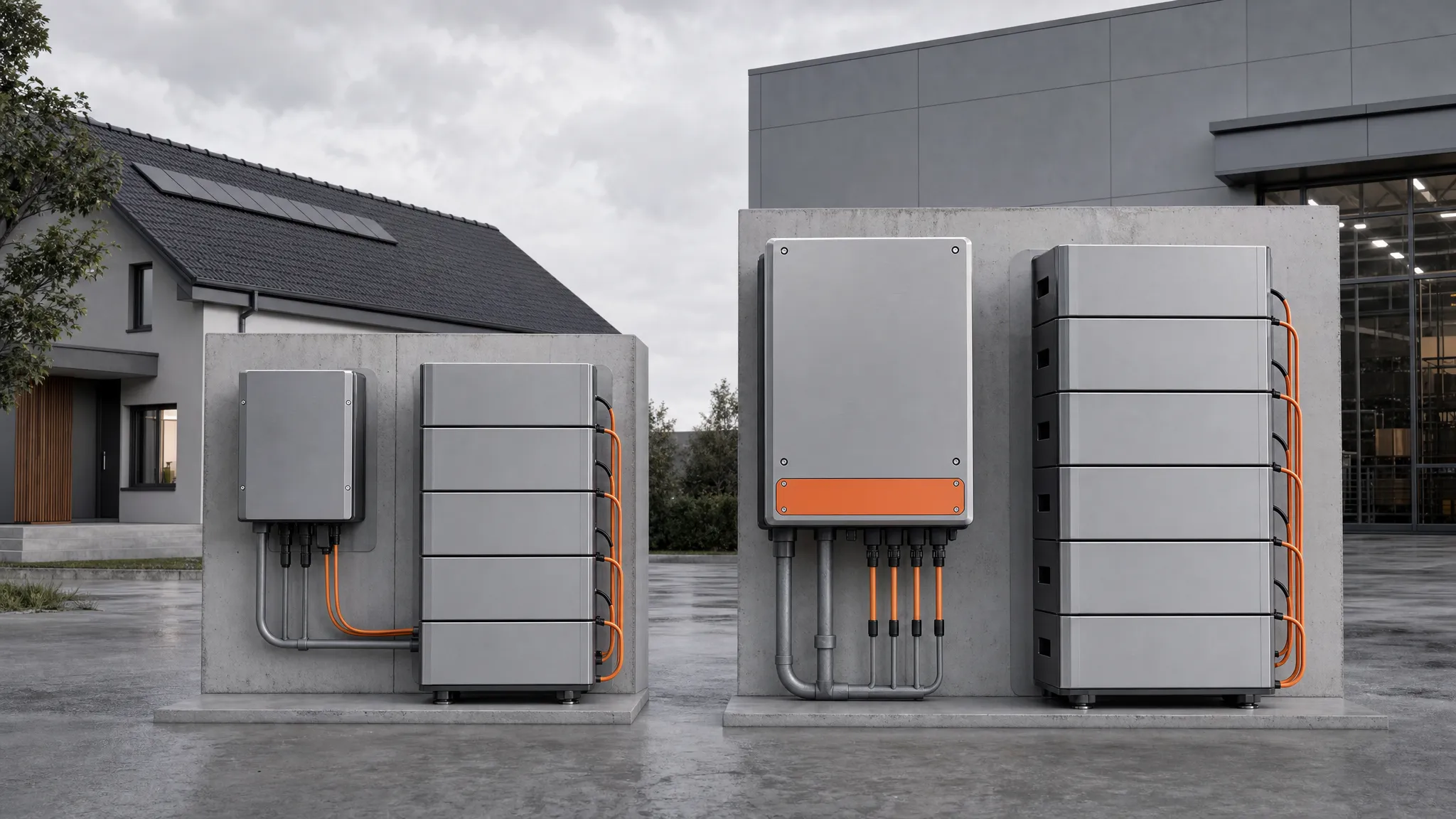
Single-phase and three-phase high-voltage hybrid inverter architectures differ on the AC side, not the battery side.
Three AC-side numbers belong in the same worksheet as the DC ones:
- Backup transfer time. Residential units often publish a figure in the 10 ms class for the transfer to backup power; commercial equipment can be slower. Motors and IT loads care about this number.
- AC passthrough rating. A three-phase unit rated for 150 A of continuous AC passthrough can carry a large share of the site load, which changes the protection scheme.
- PV input or none. A hybrid inverter with MPPT inputs expects PV strings on that side, while an AC-coupled setup has no PV input at all and only sees the battery and the grid. Some products sidestep the choice by shipping the inverter and battery as one enclosure — an all-in-one home battery has no separate pairing decision to make, and that is its main advantage at small scale.
Above the residential class, the pairing question becomes a power conversion system question, and the selection criteria shift toward reactive power, grid-code profiles and enclosure rating. Those are covered in this commercial PCS selection guide for 50–500 kW systems.
Step 5 — Confirm the Certification Story for the Pair, Not the Parts
Certification is where the phrase "it is all certified" does the most damage.
Three layers exist, and holding one does not grant the next:
Layer | Typical standard | What it covers |
|---|---|---|
Battery component | UL 1973, IEC 62619 | The battery's own safety as a stationary unit |
Inverter component | UL 1741, IEEE 1547 | The conversion equipment and how it interlocks with the grid |
Complete system | UL 9540 | The battery and conversion equipment evaluated together |
UL 9540A is not a listing standard: it is the fire-propagation test method behind a UL 9540 listing.
UL's energy storage testing and certification scope describes UL 9540 as the standard for energy storage systems and equipment, and UL's announcement of the first UL 9540 certification describes it as a UL 1973-certified battery "evaluated for use with a power conversion system" — one system-level scope, not two components with certificates in a folder. IEC 62619 is the corresponding international safety standard for lithium cells and batteries in industrial applications, including stationary storage, as set out in the IEC 62619:2022 publication record. For grid-tied operation, IEEE 1547-2018 defines the interconnection and interoperability requirements a utility will ask about.
The practical consequence for a mixed-brand pair is simple: a battery with its own certification and an inverter with its own certification do not add up to a listed system. If the project needs a system-level listing, the matched pair has to be the unit of evidence.
Honesty matters here, including about our own hardware. The published approvals for the residential high-voltage stack we build are CE and UN38.3. If a project requires a system-level listing, that requirement is confirmed against the documentation of the specific battery-and-inverter pair, which is exactly why this check runs last: it depends on the four decisions above it.
The Pairing Worksheet: Fill It In Before You Ask for a Quote
Everything above collapses into one sheet. Fill in the left column from the two datasheets, then take the sheet to both vendors and ask them to confirm the right-hand column in writing.
Item | Where it comes from | Pass condition |
|---|---|---|
Battery operating window | Battery datasheet, min and max V | Sits fully inside the inverter's battery input range |
Inverter battery input range | Inverter datasheet, battery port (not PV) | Contains the battery window with margin at both ends |
Number of battery inputs | Inverter datasheet | Matches or exceeds the number of stacks you plan to parallel |
BMS protocol and version | Battery manufacturer, in writing | Appears on the inverter's supported list, with firmware version |
Battery rated / max current | Battery datasheet | ≥ the current needed for your target power at the lowest operating voltage |
Inverter charge / discharge current limit | Inverter datasheet | ≥ the same figure; the lower of the two becomes the design limit |
Phase count and service voltage | Site survey | Matches the inverter's AC output configuration |
Certification scope required | Local authority or utility | Listing level identified, and the pair is within it |
Send the completed sheet to both manufacturers. The value is not the answers — it is that a written reply creates a record of who confirmed what, which is the document you want if the pair misbehaves after commissioning.
Where Matched Pairs Still Fail After Commissioning
Five green checks do not guarantee a quiet life. Four things still go wrong, and all four are predictable.
Firmware drifts apart. Protocol support lives in firmware. An inverter update can drop a battery model from the supported list, and a battery firmware update can change how limits are reported. Ask each vendor how often their compatibility list is revised, and put a note in the maintenance schedule to re-check it after any update.
The warranty boundary lands on you. When a matched pair fails, each vendor sees a healthy product and an unhealthy counterpart. A written confirmation of the pairing, per the worksheet above, is what moves the conversation from "not our problem" to a joint investigation.
Dispatch settings cycle the battery harder than you intended. The default operating mode decides how often the stack cycles: self-consumption optimised for bill savings, time-of-use shifting, or backup reserve held in the bank. A pair that is electrically perfect can still be programmed into a short life. Decide the mode before commissioning, not after. The logic sits either in the inverter or in a separate EMS, and the monitoring layer is worth a check at the same time: if the app or the inverter's HMI reports a state of charge that disagrees with the battery's own display, the pair is probably running open-loop.
Expansion ceilings appear late. Stackable designs look infinitely expandable until you hit the maximum modules per string or the maximum parallel clusters. Buyers who size the inverter for a future battery count and the battery for today's load discover the ceiling at the second expansion. Both limits are published — sizing a scalable high-voltage battery is where that arithmetic belongs, and the modular high-voltage battery system format matters for how cleanly the second step goes in.
Whether your installation suits a wall-mounted unit or a floor stack is a separate decision, covered in this wall-mounted versus stackable comparison.
High-Voltage Battery Hybrid Inverter FAQ
What type of inverter is best for a high-voltage battery?
One whose battery input voltage range fully contains the battery's operating window, whose firmware supports the battery's BMS protocol, and whose current limits cover your target power at the battery's lowest operating voltage. Phase count follows the building service, not the battery.
What are the downsides of a hybrid inverter?
A hybrid inverter carries PV conversion, battery charging and AC output in one enclosure, so a failure takes all three functions offline at once, and the DC rating tends to be fixed at purchase. It also inherits the BMS protocol list of its manufacturer — a limitation you do not have with a separate inverter and charger.
Which battery is best for a hybrid inverter?
The one whose voltage window, protocol and current limits match that specific inverter model. There is no universally best battery, which is why this guide runs the checks in order rather than starting from a shortlist of brands.
How long does a hybrid inverter battery last?
Battery life is measured in charge cycles rather than years. The residential stacks described above use LFP (LiFePO4) cells and publish 6,000 cycles at 80% state of health; commercial cabinets commonly publish 8,000 cycles at the same threshold. Daily cycling and dispatch settings matter more than calendar age.
Can you pair brands that were not designed together?
Sometimes. The pairing is only as reliable as the communication between them, so a mixed-brand pair needs written protocol confirmation from the inverter side. Where that confirmation is not available, the fallback is open-loop operation with configured voltage thresholds — workable, but with a weaker safety envelope and no shared warranty position.
The Pairing Order, in One Paragraph
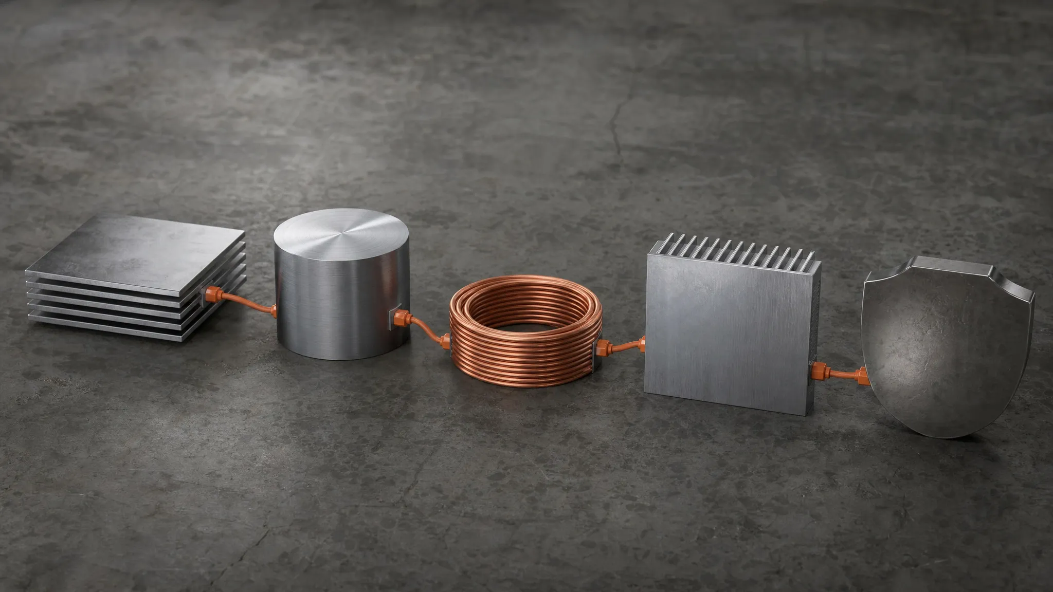
The five checks in order: voltage window, BMS protocol, current limits, phase count, certification scope.
Match the voltage window, settle the BMS protocol, check the current limits, confirm the phase count, and clear the certification scope — in that order, every time. It takes an afternoon with two datasheets and two emails, and it is the difference between a high voltage battery system that commissions cleanly and a pair that spends its first month in negotiation. If you are working through the voltage window now and want published numbers to check against, start with the stackable high-voltage storage Hua Power builds for residential projects.