

The short answer to "what is a BMS battery?" fits in one sentence: a battery management system (BMS) is the electronics and firmware between a lithium pack and everything connected to it — measuring each cell, enforcing limits the cells can survive, and reporting how much energy is left. Every commercial lithium pack of any size is sold with one, though on the smallest consumer packs it may be nothing more than a protection circuit module.
If that definition is all you need, the knowledge base explainer on what a BMS is is the canonical page — it covers the measurement physics, the protection layers and how SOC is estimated. This page is the buyer's half of the same subject. It assumes a BMS is already on your bill of materials for a commercial or utility battery energy storage system (BESS) and asks what you have to nail down before you sign: what a datasheet must state, how the BMS behaves in closed loop with the power conversion system (PCS) and the energy management system (EMS), what you can prove at commissioning, and what the warranty says about the board most likely to strand a container. If you are still building the surrounding vocabulary, the battery energy storage basics hub covers cells, racks and containers from the ground up.
What a BMS Does, in Six Lines
Strip away the marketing and a BMS performs six functions. Every feature list you will read is a variation on them.
Function | What the BMS does | What fails without it |
|---|---|---|
Measurement | Samples cell voltage, pack current and module temperature continuously | Protection decisions run on stale data |
Protection | Opens contactors or commands the converter to stop at a limit | Overcharge, over-discharge, overcurrent, thermal events |
Balancing | Moves or burns off charge so cells converge | Capacity loss; the weakest cell sets pack range |
State estimation | Calculates state of charge (SOC) and state of health (SOH) | Runtime and warranty claims become guesswork |
Communication | Reports limits and status to charger, inverter, power conversion system (PCS) or energy management system (EMS) | The converter charges blind |
Records | Logs faults, events and cycle history | Field failures cannot be diagnosed |
Protection is the function that matters legally and commercially. A cell driven above its upper voltage or below its lower voltage degrades quickly, and a pack charged outside its temperature window can enter thermal runaway. UL Solutions evaluates the BMS as part of the battery system when a pack is tested to UL 1973, and separately offers functional safety assessment for battery management systems — because the software that decides to open a contactor is itself a safety function.
That is the whole functional story. What follows is what changes when you are buying five megawatt-hours of it rather than reading about it.
Where the BMS Sits: Cell, Module, Pack
A 100 kWh pack is a few hundred cells grouped into modules, then into strings. The BMS mirrors that hierarchy — which is why "how many cells does it monitor" is the wrong question, and "how many channels per level" is the right one.
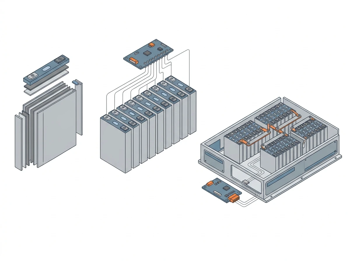
At cell level the analog front end reads every series element in its group. At module level a board aggregates 12 to 16 cell readings, a couple of NTC thermistors and a balancer, then reports upward. At pack level a controller adds string current, contactor state and insulation resistance. Above that sits the system controller or the EMS.
Two numbers set the channel budget: series cells per string, and strings in parallel. A 16-series LFP module is 51.2 V nominal — the number behind most 48 V-class home batteries, which low-voltage home storage explains from the system side. Fifteen in series gives 768 V, a common commercial cabinet voltage. Four hundred and sixteen cells in series gives a nominal 1,331 V, which is the configuration inside a 5 MWh container: twelve parallel clusters of 416 cells, just under 5,000 cell groups to monitor, all on isolation-rated sensing. Hua Power's HC-UPSB5010L container is an example, certified to UL 1973, UL 9540 and UL 9540A.
Change the cell count and you change the isolation rating, the sense-wire count and the cost of every board in the chain. The wiring logic is covered in series vs parallel battery configurations.
Three Architectures, and What Each Costs in the Field
The architecture question is really about where the sense wires end and the data bus begins.
Architecture | How it is built | Strength | Weakness |
|---|---|---|---|
Centralized | One board carries every cell input | Cheapest per channel; compact | Long high-voltage sense looms; one failure takes the pack down |
Distributed | A board per module, isolated bus to a master | Short sense wires; module swap without rewiring | More boards and connectors; higher cost |
Master-slave (rack) | Module boards → string controller → system controller | Scales to MWh; each level can isolate itself | Firmware complexity; addressing and version discipline |
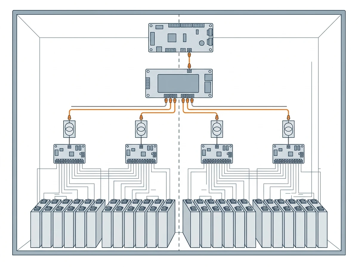
Anything above roughly 100 kWh in a cabinet lands on the master-slave form, whether the vendor calls it that or not. A home battery with four stackable modules is distributed in practice; a 20-foot container with twelve parallel strings is master-slave with three levels.
The distinction matters at procurement because it determines what is replaceable. In a centralized design a failed monitoring board means opening the whole pack; in a master-slave design a module board swaps in the field — but only if the replacement carries compatible firmware, which turns a two-hour job into a two-day one.
The Limits a BMS Enforces
Here is where most explainers stop being useful. These are the numbers a BMS works against for LFP chemistry.
Parameter | Typical LFP value | Why the limit exists |
|---|---|---|
Cell operating window | 2.5–3.65 V (3.2 V nominal) | Below roughly 2.0 V the anode potential climbs as the SEI breaks down, and on deep over-discharge past 0 V it passes the copper oxidation point (~3.4 V vs Li/Li⁺) and the copper foil dissolves; above 3.65 V cathode oxidation accelerates |
Charge temperature | 0 to 55 °C at the cell; ask for the configured value, which is usually tighter | Charging below freezing plates lithium metal |
Discharge temperature | −20 to 55 °C | Capacity and internal resistance swing widely at the edges |
Cell voltage spread at rest | ≤30 mV before balancing starts | A wider spread means one cell cuts the pack short |
Sense accuracy | ±5 mV | A protection threshold is only as good as the measurement under it |
A BMS compares each value against a threshold every cycle, typically every 100 ms to one second, and has three escalating responses: warn, derate, disconnect. Derating — telling the converter to cut current — protects revenue, because a hard trip on a hot afternoon costs the owner a dispatch cycle.
A protection threshold is only as good as the measurement under it: ±5 mV at the cell, or the whole table is fiction.
Where these numbers come from: the voltage window and temperature ranges follow a published cell datasheet for a 280 Ah prismatic LFP cell, the EVE LF280K specification — 3.65 V charge cut-off, 2.5 V discharge cut-off, 0–55 °C charging, −20 to 55 °C discharging. The spread and accuracy rows are BMS settings rather than cell data: ±5 mV at the cell is a system budget, and the monitor chips in this class do better than that in silicon — TI specifies ±1.5 mV ADC accuracy for the BQ79616, a 16-channel stackable monitor. Where your cell datasheet and the BMS defaults disagree, the datasheet wins; the cell warranty is written against it, not against the cabinet brochure.
Current limits also interact with the C-rate the cells are rated for: a BMS enforcing a conservative limit quietly caps usable power.
What the Datasheet Must State
A brochure confirms the BMS exists. These are the lines that decide whether you can operate the container for fifteen years — and the answer that should end the conversation.
Line item | What to demand | Answer that should worry you |
|---|---|---|
Protection table | Every threshold, at cell, module and rack level, with delay and action for each | "Over-voltage protection" with no level, no delay, no action |
Measurement | ±mV at the cell, the sample period, the calibration interval | Accuracy quoted at 25 °C and nothing else |
Balancing | Current in mA or A, plus the cell voltage above which balancing runs | A current figure with no start voltage |
SOC accuracy | A stated error band and the conditions under which OCV correction runs | "Accurate SOC estimation" |
Insulation monitoring | Measurement range, alarm and trip thresholds, response time | Alarm only, no trip |
Communications | Protocol, transport, message map with a revision number | "CAN — map available on request" |
Contactors and fuses | DC rating, breaking capacity, pre-charge time and resistor duty | An AC-rated contactor |
Firmware | Field update method, version recorded per board, rollback path | "Factory update only" |
Environment | Operating temperature with the derating curve, IP rating, altitude | A single temperature number, no curve |
A datasheet that answers all nine lines is not automatically a good BMS. But a supplier who cannot put four of them in writing has not specified the BMS — someone else did, at a price you will discover later.
Cell Balancing: What You Are Actually Buying
Cells leave the factory matched within a few millivolts and then age apart: temperature differences across a cabinet, self-discharge variation and manufacturing spread push them in different directions. Balancing is the slow correction.
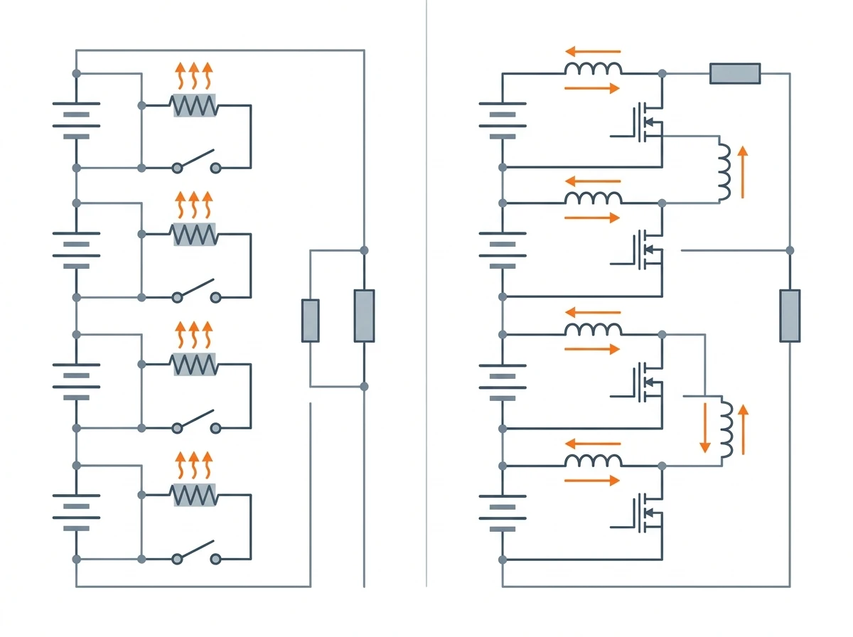
Passive (resistive) | Active (charge transfer) | |
|---|---|---|
Method | Bleeds excess charge through a resistor as heat | Moves charge from higher cells to lower ones |
Typical current | 50–200 mA | 1–5 A |
Energy cost | Bled charge becomes heat — wasted by design | Most transferred energy is conserved |
Cost and complexity | Low; one resistor and switch per cell | Inductors or capacitors per group; higher part count |
When it is enough | Systems that rest at full charge; well-matched cells | Hard cycling, long strings, weak thermal uniformity |
Two practical notes before you pay for the upgrade. Passive balancing only runs above a voltage threshold, often around 3.4 V per LFP cell, so a pack held at partial state of charge for grid services never balances at all — that is a design constraint, not a fault. And balancing current is small next to pack current: at 100 mA, correcting 1 Ah of imbalance takes ten hours. A pack that arrives with 200 mV of spread will not be fixed by any balancer; that is a cell-matching failure from the factory.
Active balancing earns its cost on long strings under hard duty. On a well-matched, liquid-cooled pack cycling at 0.5C the gain is small, and the money is better spent on thermal uniformity.
SOC and SOH Accuracy Is a Commercial Number
State of charge is not measured. It is inferred, and every method has a known failure mode.
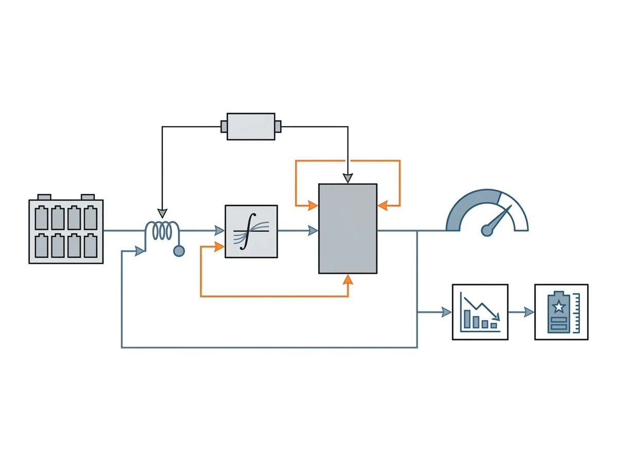
Coulomb counting integrates current over time: accurate over short intervals, drifting over long ones, because a sensor with a small offset accumulates error every hour. Open-circuit voltage lookup is accurate but needs two hours or more of rest — exactly what an operating storage system never provides. Production systems fuse the two, with coulomb counting as primary, OCV correction during genuine rest and a model-based filter in between. The methods themselves are well documented, including in Battery University's BU-908 overview of battery management systems. The gap between a good and a mediocre BMS usually shows here rather than in the protection thresholds, because protection is easy and estimation is not.
State of health is slower: measured capacity against rated capacity, plus internal resistance growth. Most warranties define end of life at 70–80 % of rated capacity, and the BMS is the instrument that decides when that line is crossed. That makes SOC and SOH accuracy commercial, not cosmetic: the number on the screen is the number in the warranty claim, and the log behind it is the evidence.
Integration with the PCS and EMS
In a container the BMS is never the only intelligent device, and most integration failures are not protocol failures.
The loop carries limits, not setpoints. The BMS publishes charge and discharge power limits, voltage and current limits, and its own state; the PCS or the EMS turns those into a dispatch command. Without the loop, the converter follows a fixed voltage and current profile and the BMS can only protect by tripping — shutdown instead of derating.
The message map matters more than the protocol name. CAN, Modbus RTU and Modbus TCP all appear in this market. What decides whether integration takes a week or a quarter is whether the supplier hands over a point list with addresses, scaling and units, and a revision number that changes whenever the map changes.
Someone has to arbitrate. When the PCS asks for 500 kW and a hot module has cut the limit to 400 kW, the BMS must win, and the precedence has to be written down. Undocumented arbitration is how a container ends up cycling outside its own limits.
Failure behavior must be defined on both sides. If the link dies mid-dispatch, does each device hold the last setpoint, derate, or trip? Holding is dangerous, derating is acceptable, tripping is safe but expensive — and the answer should be in the integration document, not discovered on site.
Multi-cluster containers need cluster-level limits. If one cluster can be isolated for service while the rest keep running, that capability comes from the BMS, and it is worth asking about before you buy twelve of them.
Commissioning and Acceptance Tests
A BMS is the one subsystem you cannot inspect after the fact, because the thresholds live in firmware. Everything below happens before you sign.
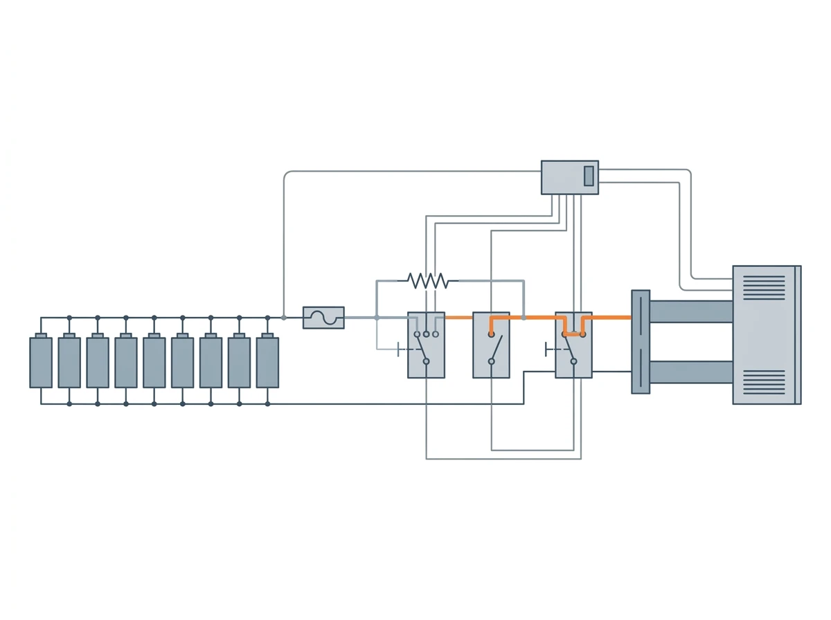
- Insulation resistance, measured and recorded before first energization, against the nameplate value.
- Protection trips, by forcing each threshold at cell and rack level and recording which device acted and how long it took. A protection table you have not tested is a claim.
- Pre-charge and closing sequence, confirming bus voltage is verified before the main contactor closes, and that repeated pre-charge attempts do not cook the resistor.
- Capacity and round-trip efficiency, at rated power, compared against the nameplate kWh and the RTE figure.
- SOC calibration, comparing displayed SOC against measured capacity, and confirming that OCV correction actually runs when the pack rests.
- Communication loss, by pulling the link at full power and recording whether the system holds, derates or trips — and how it recovers.
- Balancing, with cell spread recorded before and after a full charge cycle.
- Documentation handover: as-built protection table, point-list revision, firmware version per board, and the test records. This is the same set an authority having jurisdiction or a warranty claim will ask for later.
System-level certification then wraps the battery: UL 9540 evaluates the complete system, referencing UL 1973 for the battery, UL 1741 for the converter and IEEE 1547 for grid interconnection. Excellent protection logic still fails that evaluation if the documentation cannot show how the trip paths were verified — which is why item 8 is a commissioning task, not paperwork.
Failure Modes, Service and Warranty
Six failures account for most BMS service calls, and each carries a different cost.
Failure | How it shows up | What it should cost |
|---|---|---|
Module board drops offline | That module's readings vanish; the string continues derated if the design allows it | A board swap, hours not days — provided firmware matches |
Contactor welded shut | The pack cannot be isolated during a trip | That string out of service until the contactor is replaced |
Open sense wire | One cell reads frozen or implausible; protection is blind at that cell | Loom repair and downtime |
Insulation resistance falling | A trending alarm before the trip: moisture, chafe, condensation after a cold night | Dry-down and repair; the trip prevented a hazard |
SOC drift | Runtime disagrees with the screen; premature derating at the end of discharge | Recalibration, not a part |
Thermal or pump fault | Power limit steps down with no obvious fault code on the panel | A service visit |
Three alarms cover most service calls: cell voltage spread above threshold, insulation resistance low, and communication loss between a module board and the controller. Each becomes a two-hour diagnosis if the BMS logs timestamps, cell extremes and the state at trip. A BMS that reports only "fault" becomes a site visit.
The warranty is where the technical and the commercial argument meet, and four questions cover it. Is the BMS inside the battery warranty or a separately warranted item with its own term? What conditions does the capacity or throughput warranty carry — temperature window, SOC window, C-rate, cycle count — and does the BMS log prove compliance with them? How long are spare module boards and controllers available after delivery, and what is the lead time? And how long is firmware supported, and who may update it without voiding anything?
A fifteen-year asset on a two-year control-board warranty is a thirteen-year exposure — and the log is what any claim will be argued from.
How to Specify a BMS: Eight Questions
If you can specify, these questions separate a serious answer from a brochure.
- How many series cells per string, and what is the isolation rating of the sense path? The answer should be a number, not "high voltage".
- What is the protection table? Over/under-voltage, overcurrent curves, temperature windows, and derate-versus-trip logic for each.
- What is the balancing current, and above what cell voltage does balancing run? A pack that never reaches that voltage never balances.
- How is SOC corrected, and how often? Look for a stated OCV correction condition and an accuracy band.
- What does it publish, on which protocol, and is the message map documented? Closed-loop PCS integration without a published map is a support ticket waiting to happen.
- What happens when one module board fails? Does the string continue at reduced power, or does the rack trip?
- Can firmware be updated in the field, and is the version recorded per module? Mixed firmware is the usual cause of "it worked on the bench".
- Which standards were the BMS and pack evaluated to, and by whom? For stationary storage: IEC 62619, UL 1973, UL 9540A.
If a supplier cannot answer 2, 4 and 6 in writing, the BMS is a black box and the warranty is a promise about a black box.
FAQ
What is a BMS battery? A BMS — battery management system — is the control electronics inside a lithium pack that measures each cell, enforces voltage, current and temperature limits, balances cells and reports state of charge to the equipment using the battery.
What are the three types of BMS? Centralized (one board for all cells), distributed (a board per module) and master-slave or modular (module boards feeding a string controller and a system controller). Cabinets above roughly 100 kWh almost always use the modular form.
Which BMS is better, active or passive balancing? Neither universally. Passive balancing is cheaper and adequate for well-matched cells that rest at full charge. Active balancing pays off on long series strings, hard cycling and poor thermal uniformity.
Do all lithium batteries have a BMS? Every commercial lithium pack is sold with some form of management electronics, but on small consumer packs it can be only a protection circuit module with no communication and no state estimation — a protection device rather than a management system.
What is the difference between a BMS and an EMS? The BMS manages the battery: cells, limits, state. The EMS manages the site: dispatch, tariffs, multiple assets, and the commands sent to the BMS.
Where to Go Next
The BMS decides whether the chemistry you paid for is still usable in year eight. It is also the part most often accepted without a specification, on the strength of a one-page datasheet and a verbal assurance about "active balancing".
Sizing a system rather than specifying a controller? Start one layer down: what LiFePO4 cells actually do explains the voltage window and cycle behavior these limits are built around. And if you are comparing containers, send the eight questions above to every supplier on your shortlist — including us: talk to the Hua Power engineering team if you want the protection table, point list and test records for a specific product rather than a generic answer. The differences between the answers will tell you more than the capacity rating will.