

Why a Battery Wiring Connection Guide Should Start at the Joint
Most battery wiring connection guides stop at "connect positive to negative". A battery bank rarely dies of chemistry — it dies of a joint that ran hot for eighteen months.
A termination that is not fully seated, or not torqued to specification, has higher contact resistance than the one beside it, so it runs a few watts hotter. The heat oxidises the contact surface, oxidation raises the resistance again, and the cycle feeds itself until the lug discolours, the insulation at the neck goes brittle, or the BMS opens an alarm nobody can explain. Cells that measure fine in isolation get replaced because the fault was two terminals away.
Four failures account for most of it: a termination at the wrong torque, a conductor sized for current but never checked for voltage drop, a protective device that cannot interrupt the available fault current, and mechanical damage — chafe, UV-degraded jacket, rodent damage — on a run nobody inspected after commissioning. Everything below follows that order: size, terminate, link, protect, wire, prove.
Cable Sizing Starts With Current, Not Voltage
Battery cable sizing is a current question. Voltage sets the insulation class, current decides the copper, and amp-hour capacity never enters.
Start with the continuous current the conductor will carry, not the model number on the inverter: take the continuous DC rating at the bottom of the battery voltage window — current rises as voltage falls for the same power — then apply the 125% continuous-load margin (NEC Articles 210 and 215). A 768 V cabinet asked for 156 kW draws 156,000 ÷ 768 ≈ 203 A, and 203 A × 1.25 = 254 A is the requirement.
Two columns decide the answer — the 90 °C column, where correction starts, and the 75 °C column that caps the result at a typical battery termination:
Conductor | 90 °C copper | 75 °C copper |
|---|---|---|
6 AWG | 75 A | 65 A |
4 AWG | 95 A | 85 A |
2 AWG | 130 A | 115 A |
1 AWG | 145 A | 130 A |
1/0 AWG | 170 A | 150 A |
2/0 AWG | 195 A | 175 A |
3/0 AWG | 225 A | 200 A |
4/0 AWG | 260 A | 230 A |
250 kcmil | 290 A | 255 A |
350 kcmil | 350 A | 310 A |
500 kcmil | 430 A | 380 A |
Those figures assume three current-carrying conductors at 30 °C ambient, and both assumptions break in a cabinet: a pair of parallel sets is four current-carrying conductors and draws a 0.80 adjustment (six parallel strings would be twelve conductors at 0.50), and a container in sun runs above 30 °C, where 41–45 °C costs another 0.82. Multiply the 90 °C column by 0.656 and cap it at the 75 °C limit: 4/0 lands near 170 A, and 254 A needs 387 A before correction, so the first conductor in the table that works is 500 kcmil — 430 A, 282 A corrected. That is why cabinets use parallel sets, matched in length: two 4/0 conductors give 520 A at 90 °C, 341 A after the same factors. Verify the values against the code edition your authority having jurisdiction enforces; the NEC development pages at NFPA track the current cycle. For peak versus continuous current, see battery C-rate selection.
Voltage Drop: The Second Gate On The Same Decision
A conductor can pass the ampacity table and still be wrong. On low-voltage DC, voltage drop is usually the binding constraint.
Drop equals twice the one-way length, times current, times resistance per metre. At 75 °C, 1/0 AWG copper runs about 0.39 mΩ per metre and 2 AWG about 0.61 — the arithmetic the Victron Wiring Unlimited manual works through in its voltage-drop chapter.
A 48 V system pulling 100 A through a 15 m run loses about 1.8 V on 2 AWG — 3.8% of nominal, above the 3% branch-circuit guidance in the NEC informational notes, and enough to trip an inverter on low DC input at end of discharge, though the conductor is thermally legal at 115 A. On 1/0 AWG the drop falls to about 1.2 V, or 2.4%. That is why 48 V wiring is unforgiving of long runs and 768 V tolerates them: sixteen times the voltage, one-sixteenth the current.
Resistance rises as copper heats, so a cable measuring 2.5% cold can sit above 3% under load — and enclosure ambient is not the site drawing's ambient. The battery storage temperature range guide covers how fast the two diverge.
Lugs And Torque: The Joint Is The Component
If one paragraph gets taped inside a cabinet door, make it this one. A correct DC termination is a closed-barrel tinned-copper compression lug, crimped with the die specified for that lug and conductor, seated on a cleaned terminal and tightened with a calibrated torque wrench to the value the manufacturer publishes. Five things carry that sentence:
- Closed-barrel tinned copper, sealing the strands against wicking corrosion.
- The die matched to the lug and conductor — a hex crimp is a gas-tight cold weld; a set screw clamps one line of contact and relaxes when hot. Use the maker's tool and die, check the inspection window, and pull-test a sample from each setup.
- A cleaned terminal face, because oxidation is resistance.
- A calibrated wrench at the published value.
- A witness mark, re-checked after the first thermal cycle and at every annual service.
Torque is where installations quietly fail. Under-torque leaves too little contact force: resistance climbs, the joint heats, heat relaxes the fastener further. Over-torque is not the safe direction either — it crushes strands at the barrel mouth, cold-flows a lithium cell's terminal insert, and strips module threads, not repairable in the field. The number belongs to the hardware, not the installer's forearm: take it from the lug datasheet or battery manual, and use a wrench calibrated within twelve months.
Two details get skipped. A flat plus a locking or Belleville washer changes clamp load at a given torque, so follow the manufacturer's washer stack; and fasteners relax after the first thermal cycle, so re-torque at the first service visit, then annually, recording the values. Grease the assembled joint, not the contact faces.
LFP modules add a wrinkle: most use threaded inserts or welded studs rather than lead posts, so the terminal is a smaller fastener with a much lower torque value and no tolerance for over-tightening. The LiFePO4 battery guide covers cell chemistry and cycle life; if you are still choosing the battery, start from the battery energy storage basics hub.
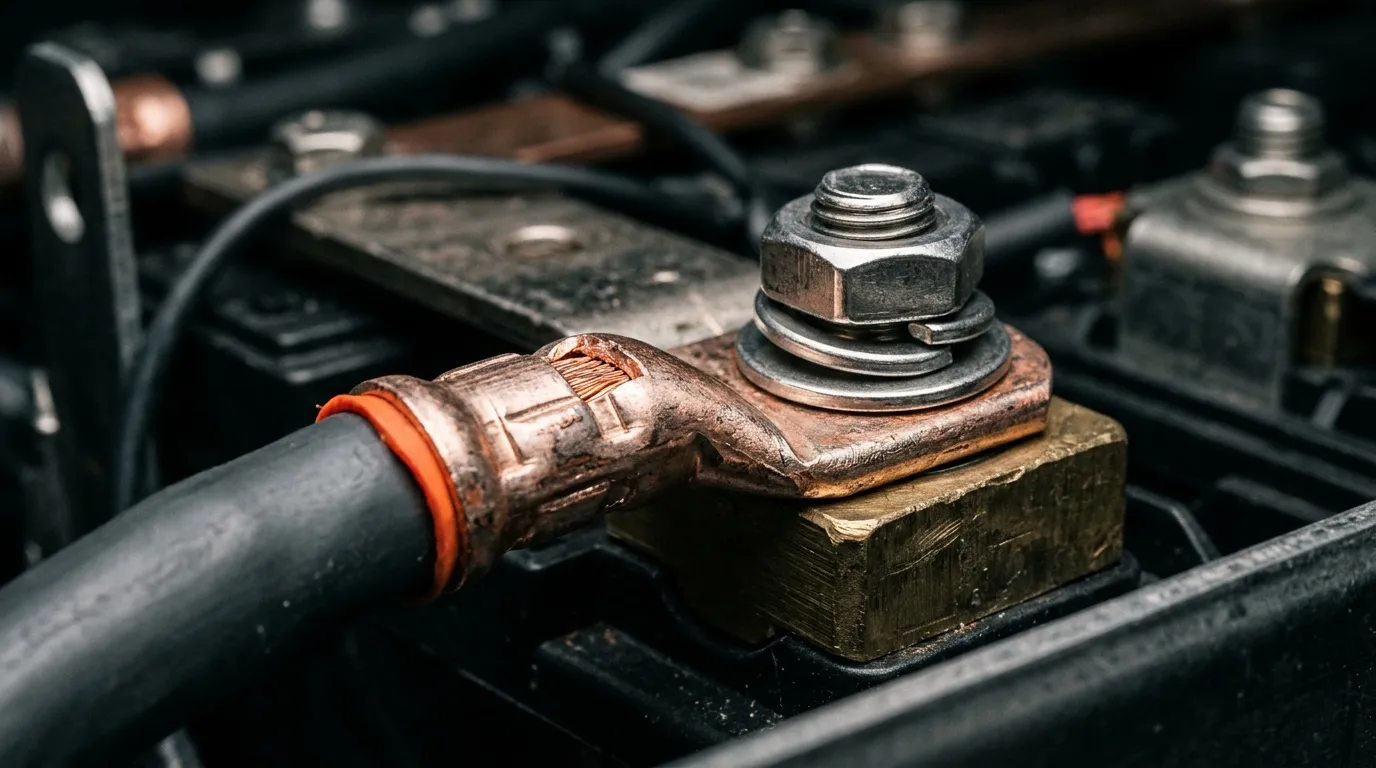
Five connector types cover nearly every joint in a cabinet:
Connector | Use it where | Failure mode |
|---|---|---|
Closed-barrel compression lug | Heavy DC cable to post, busbar or stud | Undersized die; strands splayed at the mouth |
Set-screw or mechanical lug | Field repair or aluminium, no crimper | Contact relaxes, screw backs out |
Threaded insert or welded stud | Module-to-module links on LFP | Over-torque strips the insert |
Bolted busbar lug | Many strings on a short pitch | Bimetallic contact, or a fastener too large for the bar |
Spring-clamp terminal | Sense leads, small control and comms | Insulation trapped under the clamp |
Crimp where you can, busbar where the joint must be inspected later — never a set screw on a full-current joint.
Busbar Or Cable Link?
The choice between cable link and busbar is current-and-access, not cost.
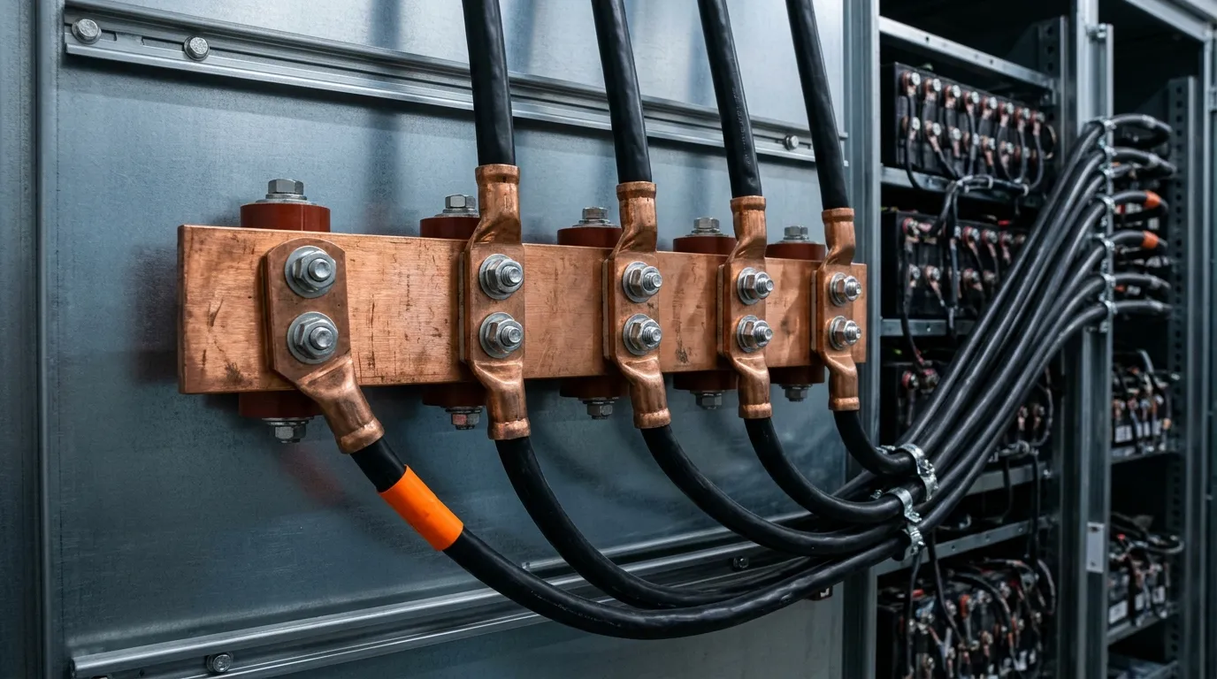
Cable links suit two bodies, a long distance, or a field termination where the only tool is a crimper. A busbar suits many parallel strings on a short pitch, high aggregate current, and any joint somebody will inspect later. Above roughly four parallel strings on one rack it is usually simpler: one flat conductor replaces a fan of heavy cable, shortens each current path, and gives every string the same electrical distance to the take-off.
In a parallel bank the string closest to the take-off carries more current, because it sees less resistance; over years it reaches end of voltage first and drags the bank with it. Equal-length links run in a star from a common point, or a busbar with every string landed at even intervals, fix that geometry. The cells need matching too: strings joined in parallel should first be matched on age, type and internal resistance, since equal-length cable corrects the path, not the cells. The maths behind parallel and series configurations lives in batteries in series vs parallel; topology is half the answer, wiring geometry the other half.
Busbar joints get the same treatment as lugs, plus two busbar-specific mistakes: mixing aluminium and copper without a bimetallic interface, which makes a corrosion cell in a damp cabinet, and bolting a lug onto a busbar too thin for the fastener.
Fusing, Breakers And Disconnects: Where The Protection Sits
Protection goes at the source end of the conductor it protects. For a battery string, the fuse or breaker sits as close to the battery terminal as the enclosure allows, so a fault anywhere along the run is cleared without the cable becoming the fuse.
Sizing runs the cable arithmetic in reverse. A 254 A continuous draw wants a device at or above 254 A and at or below the conductor's corrected ampacity — on the parallel 4/0 pair rated 341 A after correction, that is a 300 A Class T. Then the rating that separates a real installation from a plausible one: a lithium bank delivers thousands of amps into a bolted short, because the chemistry has low internal resistance. The device must interrupt more than the fault current available at its terminals, or the fault welds the contacts closed and the device becomes copper. Class T DC fuses exist for that reason; a small automotive fuse is not protection for a bank of this class.
Breakers carry the same obligations: DC-rated at the system voltage, polarised where the design requires it, with an interrupt rating suited to the available fault current. A DC breaker rated for 48 V on a 768 V bus is a switch, not a breaker.
The disconnect should isolate the battery from everything downstream in one lockable operation, positioned so the operator sees battery and isolation point together. It does not replace the fuse, and the fuse does not replace it. NFPA 855 sets the installation requirements for stationary energy storage in the US, and the disconnect, marking and separation provisions sit there rather than in the installation manual alone.
BMS Sense Harness And Communications Wiring
The BMS is only as good as the wires feeding it.
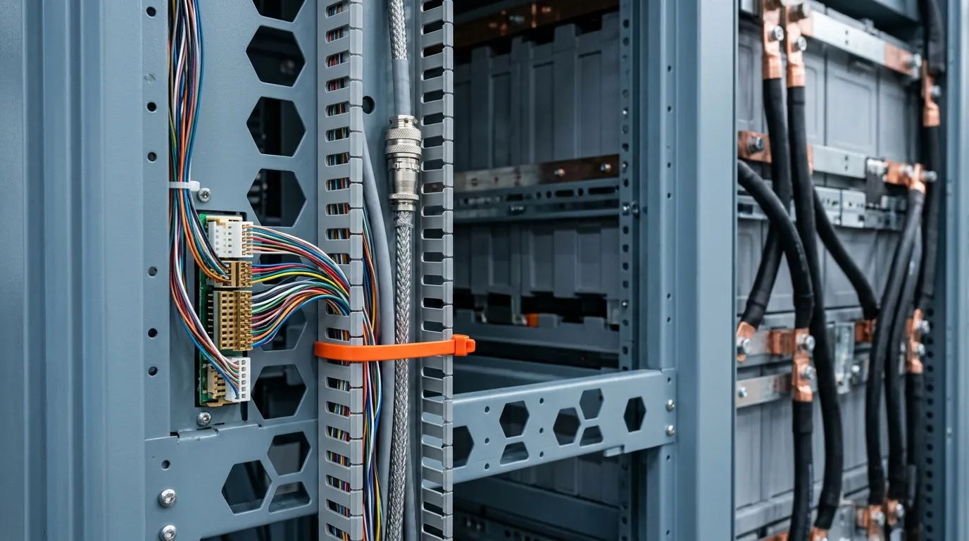
A BMS wiring harness carries two classes of signal that should not be treated alike. Sense leads are high-impedance measurement connections, one per cell or module terminal, landed in the order the BMS expects. Swap two adjacent leads and you get cell voltages that drift plausibly, phantom over-voltage alarms, and balancing that chases a fault which does not exist. Land one lead per terminal, torque the ring terminal to the maker's specification, and fit the inline fusing the harness design calls for.
The communications pair is a different problem. CAN and RS485 links between battery and inverter or EMS belong on shielded twisted pair, shield bonded at one end only, a termination resistor at each physical end of the bus, addresses set before the cable is plugged in. Two mistakes recur: a bus with no termination, which works on the bench and drops frames on a long rack; and comms cable tie-wrapped against a 200 A DC conductor, coupling switching noise into the data pair. Keep separation, cross at right angles, respect bend radius.
At commissioning, read every cell voltage against a meter and confirm the BMS reports the same order before trusting any balancing data. The BMS guide covers what the system does with those measurements.
Polarity, Pre-Charge And The First Energisation
Everything before this point is reversible. The first energisation is not.
Verify polarity at the far end of the run, not at the battery. A meter at the inverter terminals, disconnect open, confirms the conductor you believe is positive arrives at the positive terminal. Cables are made in pairs by tired people, and a reversed DC connection destroys an inverter's input stage before any protection operates.
Then pre-charge. An inverter or PCS has large DC-link capacitors at zero volts; closing a disconnect straight onto them looks like a short circuit for a few milliseconds. The spike pits terminal faces, can weld a contactor, trip the BMS and damage the input stage it was meant to feed. The remedy is a pre-charge resistor — resistance in series with the closing path, bypassed by the main contact once the capacitors are charged. Where the design has none, the inverter or PCS manual gives the value and the wait time: the resistor and delay are sized against the capacitor bank, not the battery.
An insulation-resistance test on each DC run before the first close catches a cable pinched during installation — two minutes against a nuisance earth alarm later.
After energisation:
- Thermal scan every joint under load at commissioning. An infrared camera finds a hot termination in seconds — the highest-value check here, and the first dropped when the schedule slips.
- Record the torque applied, by joint, with date and wrench calibration status, then re-torque at the first service visit and annually, repeating the scan.
- Label both poles, the disconnect and every string at both ends; fault-finding is faster and lockout is safer when the label matches the drawing.
- Inspect mechanical protection — conduit, tray, gland entries, UV-exposed jacket, rodent screening at penetrations. Cable that was fine at commissioning fails at year three.

Work on an energised DC bus is a hazard, not a chore: arc-flash boundaries, insulated tools and PPE are governed by NFPA 70E, and the battery's own safety case — the thermal-runaway testing behind UL 9540A — describes what the enclosure must contain, not what the wiring must survive.
The Five Checks That Keep A Joint Inside Its Thermal Budget
In the order this guide builds them:
Check | What it settles |
|---|---|
Conductor sized for current, then checked for drop | Ampacity alone is not a pass |
Lug crimped with the right die, torqued, marked | Contact resistance holds |
Interrupt rating above the available fault current | The fuse opens instead of welding |
Harness landed in the BMS's order, comms separated | Measurements can be trusted |
Inspection routine with dates attached | The joint stays in budget after year one |
Skip one and the battery gets blamed.
Hua Power's battery cabinets span the 241.152 kWh HC-UPSB241 at 768 V through to the 5,015.96 kWh HC-UPSB5010L container. Both are DC-only battery units with no integrated PCS, so sizing and termination stay with the installer. The product range lists each family's capacity, cooling and IP rating; the per-model DC voltage and current ratings sit on the individual product pages.
Basis of this guide. Ampacity figures are NEC Table 310.16 copper values, with the 125% continuous-load margin from Articles 210 and 215 and the 3% branch-drop guidance from the Article 210 notes; conductor adjustment and correction follow the ampacity tables of the edition your AHJ enforces. Installation requirements come from NFPA 855, arc-flash practice from NFPA 70E, the enclosure thermal-runaway test basis from UL 9540A, and the torque and voltage-drop procedure from the Victron Wiring Unlimited manual and the lug datasheet.