

Two suppliers quote the same battery storage cabinet with "Sub-20 ms response" on the datasheet, and the two numbers are not the same quantity. One of them is how long the site takes to move off a failed grid; the other is how fast the plant starts pushing power when something else is regulating frequency. Both are honest. Written into one specification without a definition, only one of them will still be true at commissioning.
Sub-20 ms response in battery storage means the system changes its electrical state within roughly one AC power cycle: 20 ms at 50 Hz, 16.7 ms at 60 Hz. That single fact explains the appeal of the number and the trouble with it. Because several different events are reported under the same phrase — grid-to-island transfer, power ramp toward a setpoint, control-loop correction, and whatever instant the test engineer chose — a sub-20 ms claim is only meaningful once you know which two instants it spans.
This is the working guide to that question. It is how this cluster handles grid frequency regulation with battery storage from the angle the market pages skip: not which services exist, but how to read the millisecond figures vendors publish for the hardware that delivers them.
What "Sub-20 ms Response" Actually Measures in Battery Storage
The physics is unglamorous. A 50 Hz grid completes one full voltage cycle every 20 ms. Most industrial loads carry enough stored energy on their DC bus — drives, rectifiers, LED supplies, control power — to ride through a missing half-cycle without noticing. Lose a full cycle and some of it does notice.
That is where the number comes from. "Sub-20 ms" is shorthand for the equipment acts within one cycle, which is a real and useful class claim. On a battery energy storage system (BESS) it more often describes the switching hardware than the inverter. What it is not is a measurement: the measurement is a duration between two events, and the phrase does not name either of them.
Grid operators care about the same millisecond scale for a different reason: fast, controllable response from storage is what lets a system with less rotating mass stay stable, which is why storage is now planned into networks rather than bolted onto them. The U.S. Department of Energy's energy storage program funds the research, validation and cost work behind that shift; the millisecond claims on datasheets are its commercial shadow.
So the useful first move is not to compare numbers. It is to decide which event the number is supposed to describe.
The Four Clocks Behind One Sub-20 ms Claim
Four distinct clocks get reported as "response time." They differ by orders of magnitude in what causes them, and they are not interchangeable in a specification.
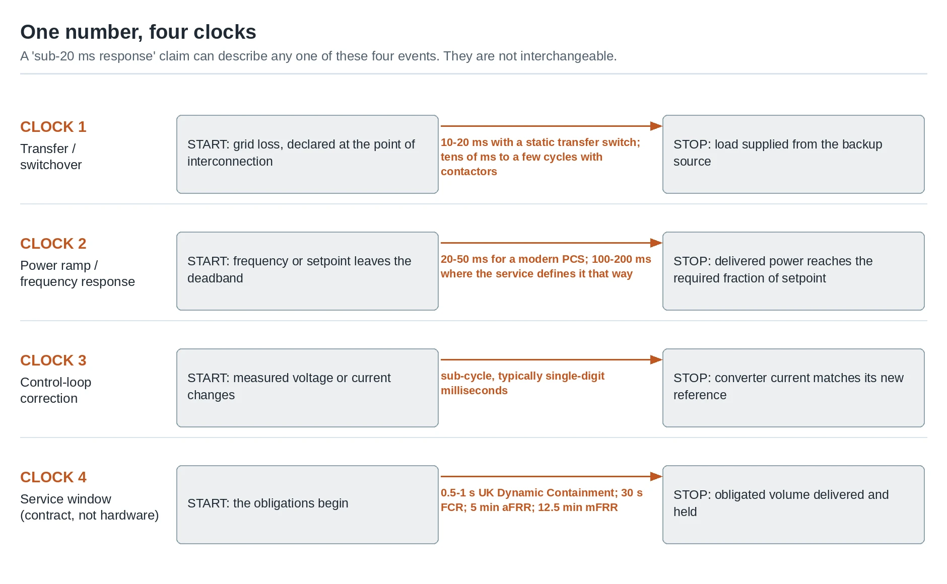
The four clocks share a name but not a duration. Each one starts and stops at a different point in the power chain.
Clock | What starts it | What ends it | Typical magnitude |
|---|---|---|---|
| Loss of the grid, or a command to island | Load is fed from the backup source | 10–20 ms with a static transfer switch; tens of milliseconds to a few cycles with contactors |
| Frequency or a setpoint leaves the deadband | Delivered power reaches the required fraction of setpoint | 20–50 ms for a modern PCS; 100–200 ms where the service is defined that way |
| A change in the measured voltage or current | The converter current matches its new reference | Sub-cycle, typically single-digit milliseconds |
| The contract, not the hardware | The obligated volume has been delivered and held | 0.5–1 s (UK Dynamic Containment), 30 s (FCR), 5 min (aFRR), 12.5 min (mFRR) |
Clock 1 is the one most people mean. It is a switching question, and the switching device decides the answer. On a quotation sheet it usually appears as seamless transfer time: the interval between losing the preferred source and the load being carried by the backup power source, with no gap long enough to reset it. A static transfer switch (STS) uses thyristors or similar semiconductors, detects the loss of the preferred source, and commutates the load in a quarter to a half cycle without a moving part. A contactor-based transfer has to break an arc and physically travel, which is why it lands in the tens of milliseconds and why the exact figure depends on the drive and the mechanism rather than on the inverter.
The distinction matters commercially, not just academically. An STS and a pair of contactors perform the same function on a single-line diagram and differ by an order of magnitude in the number a buyer will read off a cutting sheet. In an islanded microgrid where there is no utility reference to synchronize back to, the same transfer has to be performed by a grid-forming converter that creates its own voltage reference — a different mechanism with a different "response" to measure, covered in the cluster's note on island energy storage systems.
Clocks 2 and 3 are power-electronics questions. A modern power conversion system (PCS) closes its current loop in single-digit milliseconds and ramps to setpoint within tens of milliseconds. Where a project shows 100–200 ms instead, the usual reason is not slower hardware but a slower definition: the clock was started at the frequency measurement rather than at the converter.
Clock 4 is a different species. It is set by a market or a grid code, not by physics, and it is where most of the confusion that reaches a project engineer was created. Storage is unusually good at providing synthetic inertia — a controlled power injection that imitates the inertial response of a rotating machine — and other fast grid services, because the response is controllable and does not depend on fuel or rotating mass; that capability is studied at the scale of individual plants, as in this case study of a 6 MW battery system providing fast grid services.
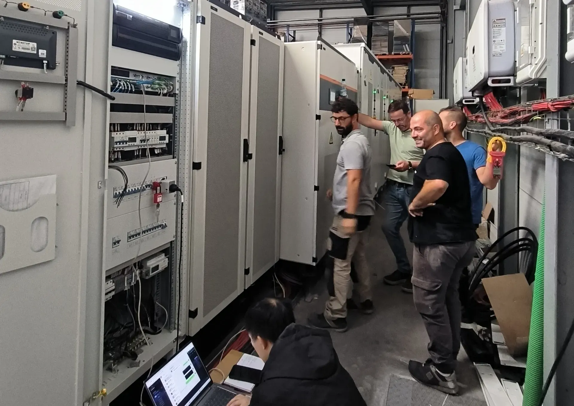
Transfer time is a property of the switching hardware inside cabinets like these, measured at the point where the load is fed — not a property of the battery.
Five Questions That Turn a Datasheet Claim into a Spec
A vendor's "sub-20 ms" survives contact with a project only after five answers. Ask them in this order and the ambiguity disappears.
1. Which clock? Force the answer into one of the four above. "Transfer from the grid to backup, measured at the load terminals" is an answer. "Response time" is not. If the datasheet mixes a transfer figure with a frequency-regulation claim, treat the two as unrelated — they are usually sourced from different tests on different equipment.
2. Where does the clock start? Candidate start points, all defensible, all different: the instant the grid voltage crosses a threshold; the instant the islanding detection declares; the instant the controller issues the transfer command; the instant the measured frequency leaves the deadband. The most common inflation is to start the clock at the detection threshold and report a switching time, which quietly omits the detection window itself.
3. Where does it stop? Candidate stop points: the transfer command is issued, the new source is connected, the load voltage is restored, or the load voltage is restored and within tolerance of nominal. A claim that stops at "command issued" can be met by hardware that still leaves a load in the dark for several cycles. Ask for the stop point in the same sentence as the start point.
4. Measured where, with what? The measurement point should be the point that has the obligation. If the contract is with the utility at the point of interconnection, a figure measured at the converter terminals is not the same number. Instrumentation matters too: at this scale a spot reading on a display proves nothing. A recording at high sample rate, with the event, the timestamps and the thresholds visible, is the only useful evidence.
5. Under what conditions? The honest answer is never a single number. Sub-20 ms transfer claims are typically quoted for critical loads at a defined depth of discharge — how much of the usable capacity has been spent — and a defined temperature. Ask for the figure at the bottom of the specified state-of-charge band, at the hot end of the ambient range, and with the site's actual starting load. A 20 ms transfer into a stopped motor bank and into a running one are different tests.
Where the load is a data center or precision manufacturing line, the requirement usually tightens below the commercial-site default, and the specification should say so explicitly rather than inheriting a brochure figure.
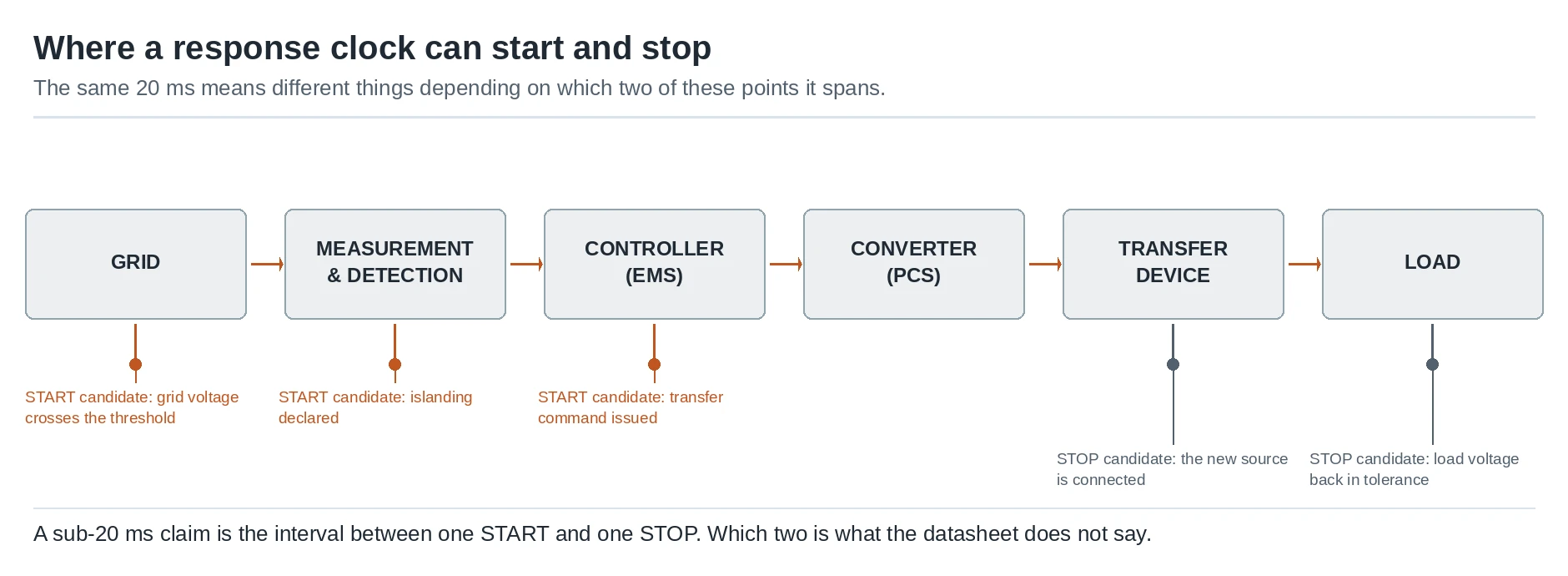
Questions 2 and 3 are really one question: which two of these points does the clock run between?
What Actually Sets Each Clock
Once the clocks are separated, it becomes possible to talk about what moves them. Five things usually decide the number.
The detection window. Frequency and voltage are computed over a window, and a shorter window detects faster but is noisier. Anti-islanding and ride-through requirements push in the opposite direction from speed: a converter that reacts to every transient will nuisance-trip, so the ride-through rules deliberately define conditions under which a plant must not disconnect. In North America that obligation has just been re-scoped, and the scope matters more than the date. NERC PRC-029-1, which sets the frequency and voltage ride-through requirements for inverter-based resources, applies from 1 October 2026 to bulk-electric-system resources and to non-BES resources of 20 MVA or more connected at 60 kV or above — for that non-BES group the compliance date is deferred to the later of 1 January 2027 or the standard's effective date; under the standard's implementation plan it retires the generator ride-through standard it replaces. A transmission-connected battery plant falls inside that scope. A behind-the-meter commercial cabinet does not: its ride-through behaviour is governed by the utility's interconnection agreement and IEEE 1547 instead. Ride-through and fast transfer are both time-domain requirements, and they constrain each other.
The control path length. Sensor, controller, communications, converter. A hard-wired analog or a fast deterministic link is measurably faster than a path that traverses meters, a gateway, and a supervisory layer before reaching the converter. Where the plant runs on an EMS, the control architecture is part of the response budget — the EMS platform architecture determines whether the loop is closed locally or goes through a supervisory layer. Droop settings and the deadband around nominal frequency are effectively deliberate delays, and they are chosen for stability, not for the response figure.
The switching mechanism. As above, semiconductor transfer and mechanical transfer are different products. This is the single largest lever on clock 1.
The load. Motors starting on the islanded bus draw inrush current several times their running current; variable-speed drives may ride through a short interruption or may not, depending on their own DC bus design. The transfer time the plant can actually achieve is limited by what the backup source can pick up, not only by how fast the switch moves. This is where a sub-20 ms claim meets reality: the switch may transfer in 15 ms and the bus may still sag because the load was harder than the test assumed.
Grid-code and interconnection requirements. Connection codes define the parameters that count at the point of compliance, and they impose timings of their own — response delays, ramp rates, and the conditions for staying connected. In Europe these come from the ENTSO-E network codes family; in the US, storage interconnection is governed by standards such as IEEE 1547 together with the utility's own requirements.
Auxiliary systems rarely set the clock, but they can break it: a thermal design that cannot sustain the duty is the usual reason a fast response is unavailable on the fifth consecutive event rather than the first. Liquid cooling is a durability answer rather than a speed answer, and it should be assessed as such. The same caution applies to the rest of the asset's duty cycle: a cabinet that also does peak shaving, backup power or a demand response obligation will spend most of its life doing none of those things quickly, and the clock that decides its economics may not be the clock on the front of the brochure.
What Sub-20 ms Is Not: Placing It on the Service Ladder
The most expensive misreading of this number is treating it as a frequency-regulation claim. It is not, and the gap is three orders of magnitude.
European frequency response is a stack of reserves, and each layer has its own obligated window. FCR (frequency containment reserve) must be fully activated within 30 seconds of a deviation. aFRR (automatic frequency restoration reserve) must show a response within 30 seconds and reach full activation within 5 minutes: the activation delay sits in Commission Regulation (EU) 2017/1485, and the 5-minute full activation time in the ACER implementation framework for the aFRR standard product, adopted under the EU Electricity Balancing framework that harmonises those products. mFRR is activated manually, on a harmonised full activation time of 12.5 minutes across the European balancing platforms, though some national markets still operate to their own timelines. In Great Britain, Dynamic Containment requires a provider to start delivering within half a second and reach full contracted output within one second, sustained for up to 15 minutes.
Layer | Obligated window | What a 20 ms PCS contributes |
|---|---|---|
Converter control loop | Sub-cycle | Everything — this is the hardware's own clock |
Grid transfer / island mode | 10–20 ms | Everything — the load never sees a full missing cycle |
UK Dynamic Containment | 0.5 s to initiate, 1 s to full output | A large margin; the binding constraint is control and metering |
FCR | Full activation within 30 s | A very large margin; the constraint is energy and prequalification |
aFRR | Response within 30 s, full activation within 5 min | A very large margin; the constraint is setpoint tracking and state of charge |
mFRR | 12.5 min harmonised (10–15 min in some markets) | Irrelevant to the outcome |
Read that table the other way and the commercial point appears. A system that transfers in 20 ms is comfortably inside every one of these windows. So the margin the number buys is real but it is not scarce — which is exactly why the definition of the number, rather than its size, is what a specification should pin down. The cluster's notes on the individual services make the same point from the market side: Dynamic Containment in the UK is decided by control quality and metering, and aFRR in Germany turns on setpoint tracking and state-of-charge management rather than on raw switching speed.
Three things the number is definitely not:
- Not a UPS classification. Uninterruptible power supplies are graded by their own transfer classes, and a storage plant claiming a UPS-like transfer is asserting a function, not a certified class. If the load is genuinely critical, ask which transfer class is being offered.
- Not evidence of efficiency or of duration. Round-trip efficiency, C-rate and energy-to-power ratio are separate quantities that determine how long and how often the plant can act. A fast clock on a small energy buffer is a fast clock that runs out.
- Not a safety test result. Tests such as UL 9540A address thermal runaway behavior, and grid-code compliance addresses interconnection. Neither one validates a millisecond figure, and a document listing both should not be read as doing so.
Nor is it a single number across markets: on a 60 Hz system a full cycle is 16.7 ms rather than 20 ms, so a figure quoted from a 50 Hz test is not automatically the same claim at a US site.
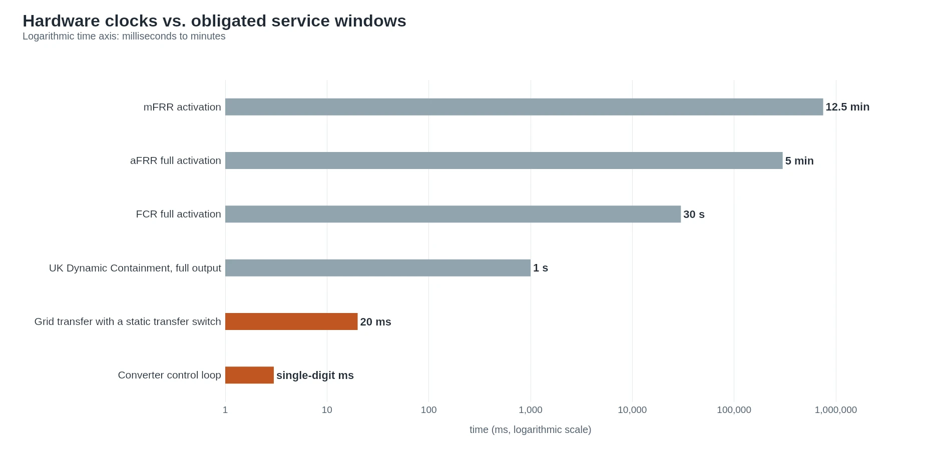
Placed on one logarithmic axis, the obligated service windows sit far above the hardware clocks — which is why the definition of the number matters more than its size.
How to Verify a Sub-20 ms Claim at FAT and Commissioning
A datasheet figure is a claim about a test nobody has seen. The point of a factory acceptance test is to replace it with a measurement, and the test is easier to run than most buyers expect.
Fix the events before the equipment arrives. Write the start and stop events, the measurement point, the thresholds, the required fraction of setpoint and the conditions into the test plan. Every party should be able to read the plan and produce the same number.
Instrument at the measurement point, not at the HMI. Record voltage and current at the point that carries the obligation, at a sample rate high enough to resolve single milliseconds, together with the discrete signals for grid loss, the transfer command and the new source closing. The timestamped recording is the deliverable; a screenshot is not.
Run the boundary cases, not the easy one. The informative tests are the ones at the edge of the specified envelope: the bottom of the state-of-charge band, the top of the ambient temperature range, the coldest start, and the site's real load profile including motor starts. National laboratory programs publish the methodology behind this kind of validation work, and the Sandia energy storage test and evaluation publications are a practical reference for what a defensible measurement program looks like.
Verify the metering chain as well. Where a service is settled on metered data, the accuracy and time synchronization of the measurement chain is part of whether the plant gets paid for acting quickly. A converter that responds in 15 ms with a meter that logs on a slow interval produces evidence that argues against the plant. Check what the site's SCADA or EMS actually records, too: if telemetry is written on a slow scan, the plant's own record of a fast response is weaker than the response itself.
Then repeat it on site. A factory test proves the equipment; a commissioning test proves the installation. Cable runs, protection settings and the actual load are all different in the field, and a plant that passed a clean factory test can still fail to hold its transfer time into a real motor bank.
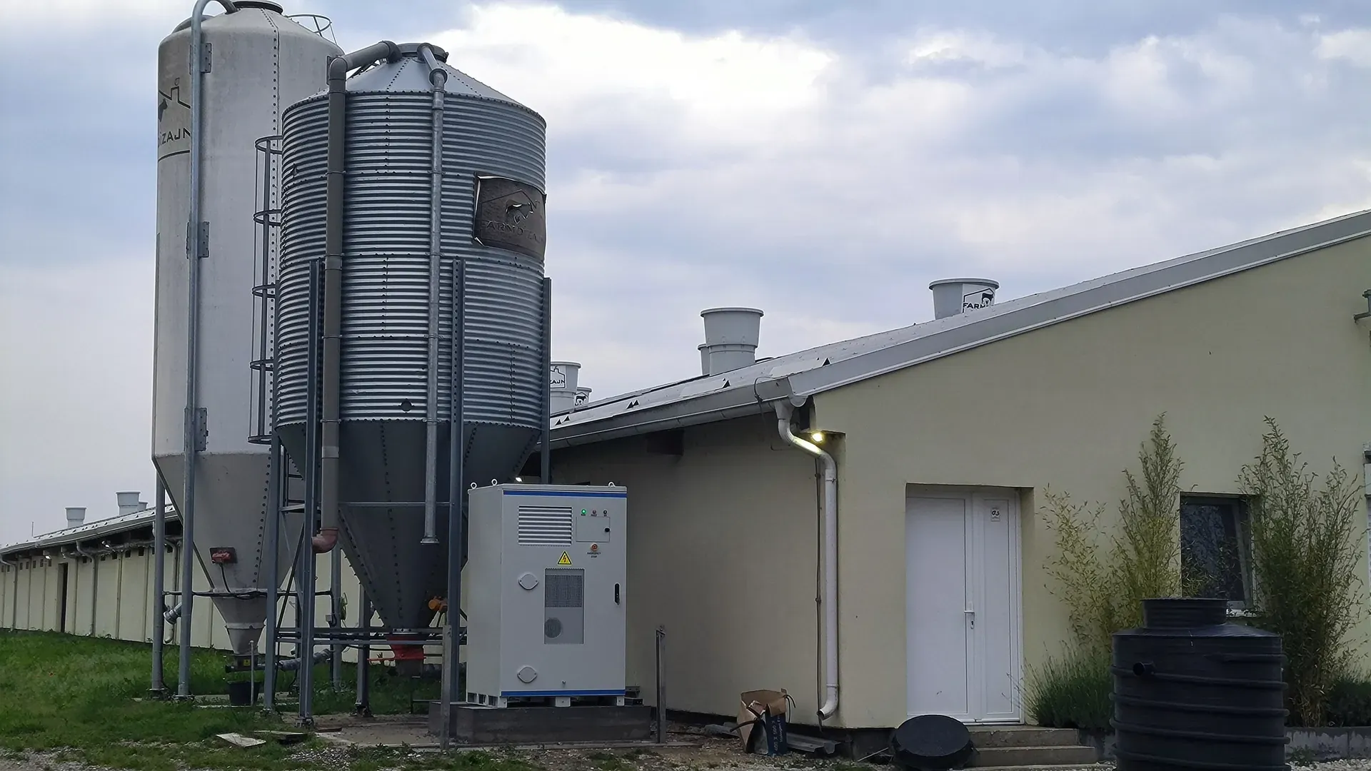
The factory test proves the equipment; a site like this is where the figure has to hold with the real cable run, protection settings and starting load.
What to Write in the Specification
The entire article reduces to four lines that close the ambiguity. They can be pasted into a technical specification as written:
- The transfer function shall complete from loss of the preferred source, declared at the point of interconnection, to the load being supplied from the backup source within the declared tolerance, in not more than 20 ms, measured at the load terminals.
- The power response function shall reach 90 percent of the commanded setpoint within ___ ms of a step change at the controller, measured at the converter terminals.
- Both figures shall be demonstrated in a recorded factory acceptance test at the minimum specified state of charge and maximum ambient temperature, and re-demonstrated at site commissioning under the actual load profile.
- Compliance with requirements at the point of interconnection shall be demonstrated against the applicable grid code and interconnection standard for the project's jurisdiction.
Line 4 is worth naming precisely rather than generically, because it decides what "response" means legally. Depending on the market, that means IEEE 1547 as applied by the utility, the European connection codes, or a transmission operator's own prequalification specification.
For a worked example of how a supplier can state the same thing honestly, our own line separates the figures by function: liquid-cooled containers such as the 1 MW / 2.089 MWh HC-UPSA2089L are specified for off-grid switchover under 20 ms, while the 125 kW / 241.152 kWh HC-UPSA241 cabinet transfers on-grid to off-grid through a static transfer switch rated at 20 ms. Those are clock 1 figures. They sit on the same datasheets as a separate, larger claim — sub-30 ms response for FCR, aFRR and mFRR duty on the grid frequency regulation range — which is a clock 2 figure. Two numbers, two clocks, two tests.
That is the pattern to demand from every supplier: one figure per clock, each with its start point, stop point and measurement point attached.
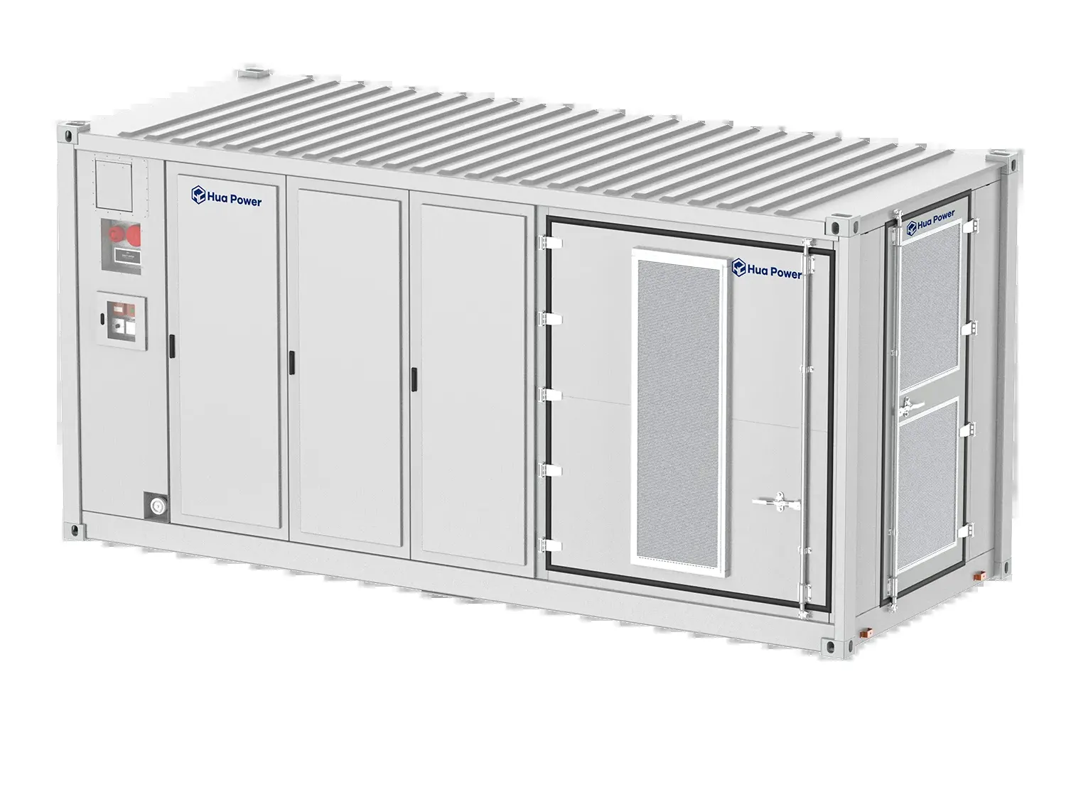
A transfer figure belongs to the switching architecture inside the enclosure, not to the cell chemistry — which is why it is quoted per product, not per battery.
The Clock Your Project Actually Needs
Which clock matters is decided by what your site has to survive, not by the smallest number available.
Your situation | Clock that matters | What to insist on |
|---|---|---|
Critical process, data center, precision manufacturing | Clock 1, transfer | Static transfer switch, a stated transfer class, and a test at the real load |
Behind-the-meter site protecting motors and drives | Clock 1, transfer | Transfer time measured with a representative starting load, plus ride-through settings |
Microgrid with no utility reference to synchronize to | Clock 1, transfer | Grid-forming capability and a black start sequence with its own timings |
Frequency-regulation revenue service | Clock 2, power response | Setpoint tracking accuracy, state-of-charge strategy and the service's own obligated window |
Multi-revenue portfolio | Clock 2 plus the service window table | A supplier who will state each figure separately, not one "response time" |
The pattern is consistent: the number that decides outcomes is usually the one nobody defined. Ask for the start point, the stop point and the measurement point of every millisecond figure on the sheet, and treat a supplier who can answer as a different class of supplier from one who cannot.
If your project has a specific requirement and you want the response budget for a configuration in writing, our engineering team works through the questions above with buyers before a specification is locked.