
Reactive power support is the deliberate injection or absorption of reactive power at a defined point on the network, controlled against a voltage target so that voltage stays inside its limits while active power keeps flowing. The definition fits in one sentence; what decides whether a battery or an inverter can actually deliver the service is the converter's apparent-power budget and the control curve the network operator sets.
Most explanations of the term stop at the power triangle and a device list. This one follows the part that turns up in specifications and purchase orders.
What the Term Covers
Reactive power is the part of the power flow that oscillates between source and load instead of being consumed: it builds the magnetic field in a motor winding or a transformer core and collapses again fifty or sixty times a second. It is measured in var (volt-ampere reactive), kvar and Mvar. Active and reactive power combine into apparent power, S = √(P² + Q²), which is why a converter is rated in kVA rather than kW.
Support means producing or absorbing that reactive power on purpose, at a named point, under a control loop that watches voltage. Injection raises local voltage; absorption lowers it. Neither changes frequency, which is the job of active power.
Four things bound the service - where, how much at that operating point, how fast, and who owns the setpoint - and all four belong in a specification.
Why Voltage Needs Reactive Current
On an AC network, voltage is a reactive quantity. Across a predominantly inductive line the voltage difference between the two ends is driven by the reactive flow between them, roughly Q ≈ V·ΔV / X. Megawatts set frequency; megavars set voltage.
Two consequences follow. First, reactive power is local: moving it any distance costs losses and drags voltage along the way, so support has to be delivered near the problem. Second, the grid consumes it. Transformers draw reactive power in proportion to leakage reactance and loading, motors draw it to magnetise their windings, and a transmission line is a net producer below surge impedance loading and a net consumer above it. Distribution feeders are mostly resistive, so reactive current there buys less voltage change per kvar and shows up mainly as losses - which is why a volt-var curve on a 20 kV feeder and a transmission-system voltage regulator are tuned differently.
Steady-State and Dynamic Support Are Different Products
A switched capacitor bank is the cheapest source of reactive power and the slowest to arrive: banks move in steps, with a deliberate delay of tens of seconds so they do not chase transients that would pass anyway. Their output also falls with the square of voltage, so they produce least exactly when voltage is lowest.
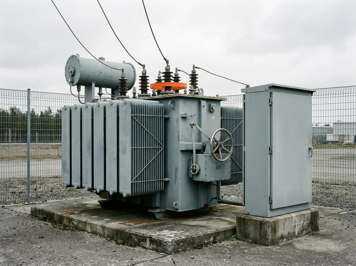
A synchronous condenser is the other extreme: a rotating machine with no prime mover, continuous in both directions, carrying real inertia and fault current at the cost of losses and maintenance. Between the two sit static compensators and, at the small end, the converters inside a battery or a solar plant.
The event that separates them is voltage collapse. When air-conditioning compressors stall during a depressed-voltage event they draw several times their normal reactive current, and switched capacitance cannot arrest it: the reactive power has to be online before the event and arrive in cycles.
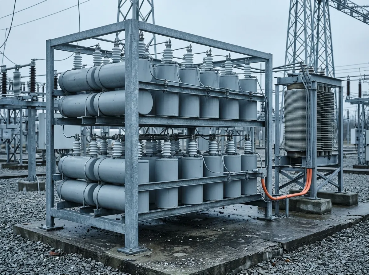
A battery sits on the dynamic side of that line by construction. What it is not is unlimited, and the limit is arithmetic.
The Converter's kVA Budget
The rating on the datasheet is apparent power, and current is what the hardware limits. Active and reactive output share that current, so every megavar a converter produces is a kilowatt it cannot produce at the same time. Converter, inverter and PCS all name the same stage.
At unity power factor the whole kVA goes to watts and reactive capability is zero. Oversize the converter against the battery and the picture changes: a unit rated at 1.2 times its active rating can hold √(1.2² − 1²) ≈ 0.66 per unit of reactive power while still delivering full active output. That is the commercial argument for oversizing, and it is a curve rather than a number - capability narrows as terminal voltage moves off nominal and as ambient temperature climbs.
The other end of the curve is worth as much and is usually missing from quotations. With active power at zero - a battery at rest, a solar plant after dark - the full kVA is available for reactive power, provided the converter stays energised and its auxiliary load is covered. A plant switched off at night provides nothing, whatever its nameplate says.
Which is why "power factor 0.9 leading and lagging" is an incomplete specification: it does not say at what active power, at what voltage, for how long, or whether the converter stays connected at zero output. What belongs in its place is the P-Q capability chart, drawn at the point of connection and at the specified voltage limits.
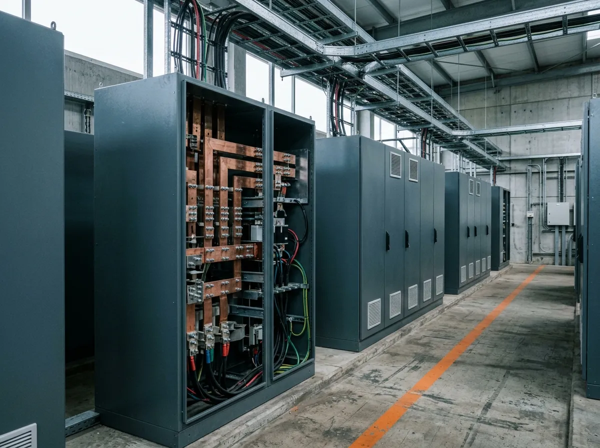
One further distinction matters for control. A grid-following converter measures the voltage already there and pushes current in step with it; a grid-forming converter sets voltage itself and lets current follow. In a weak network - one with a low short-circuit ratio - the first depends on a phase-locked loop that can become the least stable part of the plant (grid-forming inverter).
Reactive Power Support Versus Power Factor Correction
The two are confused because both are measured in kvar, both involve capacitors, and both get filed under reactive power compensation. Power factor correction is load-side: a plant installs capacitance to cancel its own inductive demand, avoid a utility penalty and cut its losses. It is sized to the load and dispatched by nobody outside the meter.
Reactive power support is a network-side service delivered at the point of interconnection, in both directions, on command, with a response time attached. The same device can do both, which is exactly why the distinction has to be drawn in the contract.
Source | Where the reactive power comes from | Direction | Speed | Output as voltage falls |
|---|---|---|---|---|
Switched capacitor bank | Charge stored in capacitors | Injection, in steps | Tens of seconds | Falls with the square of voltage |
Synchronous condenser | Field current in a rotating machine | Both | Sub-cycle to seconds | Holds, within its capability curve |
STATCOM | Switched power electronics, voltage source | Both | Sub-cycle | Holds down to low voltage, current-limited |
SVC (TCR / TSC) | Switched reactors and capacitors | Both | 1-2 cycles | Falls with the square of voltage |
Battery converter (PCS) | Current within its kVA rating | Both | Sub-cycle | Holds within the current limit |
The battery row is the one that changes procurement. A storage system is bought for energy services - peak shaving, arbitrage, reserve - and reactive capability arrives as a by-product of the converter, so it is often left unquantified (peak shaving).
What Interconnection Rules Actually Require
In the United States, IEEE 1547-2018 covers reactive power capability and voltage and power control requirements for distributed energy resources. The interconnection agreement then names the mode - constant power factor, constant reactive power, voltage-reactive power (volt-var) or active power-reactive power (watt-var) - with the curve, the deadband and the response time. The requirement sits at the point of common coupling, not at the converter terminals.
Europe takes the same shape through the Requirements for Generators network code, which makes reactive capability a condition of connection and leaves the envelope and setpoints to the relevant system operator. In wholesale markets the service has a longer history: the US Federal Energy Regulatory Commission treats Reactive Supply and Voltage Control from Generation Sources as an ancillary service, one of six identified in Order No. 888 in 1996. In 2021 it opened a Notice of Inquiry (Docket RM22-2) into how that capability should be paid for (FERC, ancillary services).
For a buyer the reading is the same everywhere: a capability at a metered point, with a curve and a time constant, commanded by somebody other than the plant owner. The energy management system carries the setpoint; the converter has to follow it.
What It Costs, and Where It Stops Working
Reactive support is not free, and the cost never appears on an energy invoice.
- kVA you never sell as energy. Oversizing a converter by 20 percent costs money on every unit and every year of the project's life, for a service called on in a minority of hours. Some markets compensate the capability; many do not.
- Curtailment, when the margin is missing. With kVA equal to kW, reactive output comes straight out of megawatt-hours - an expensive way to hold a voltage.
- Losses. Reactive current heats cables, transformers and the converter, so it shows up in round-trip efficiency even though no energy was delivered.
- Weak networks. In a low short-circuit ratio grid, aggressive voltage control can interact with other converters and with tap changers; the capability may exist on paper and still need a study before it is enabled.
- Ambient and altitude. Converter current limits are thermal, so the reactive capability in a 45 °C yard is not the datasheet headline (thermal management).
None of this argues against the service; it argues for putting the capability curve, the derating basis and the compensation terms in one document.
What to Put in a Specification
Six questions separate a real capability from a marketing number.
- What does the network operator require at the point of connection? A range in Mvar at nominal, high and low voltage, continuous and short-time, with the metering point named.
- What is the P-Q curve at full active output? Not the power factor range - the curve, at the specified voltage limits.
- What is available at zero active power? And does the converter stay energised when the battery is at rest?
- How fast, and under whose command? Response to a setpoint step, the modes supported, and who owns the curve after commissioning.
- On what basis is it derated? Ambient, altitude, voltage, and the auxiliary load the converter needs to stay online.
- What evidence comes with it? Type-test certificates against the interconnection standard, a factory test at the specified operating points, and a commissioning test at the point of connection.
How Hua Power Scopes Reactive Power Capability
Hua Power is a battery energy storage system integrator founded in 2015 and headquartered in Shenzhen, with more than 400 projects deployed and production capacity above 2.4 GWh. The scope is the storage, the power conversion and the control layer - which is where reactive capability is decided.
The work starts from the interconnection requirement rather than a power factor figure. Three inputs fix the answer: the reactive range the network operator asks for at zero and at full active output, the voltage band over which it must hold, and whether the site keeps exporting its rated megawatts while supplying it. The third sets the kVA margin, and it is the one most often missing when a project is priced.
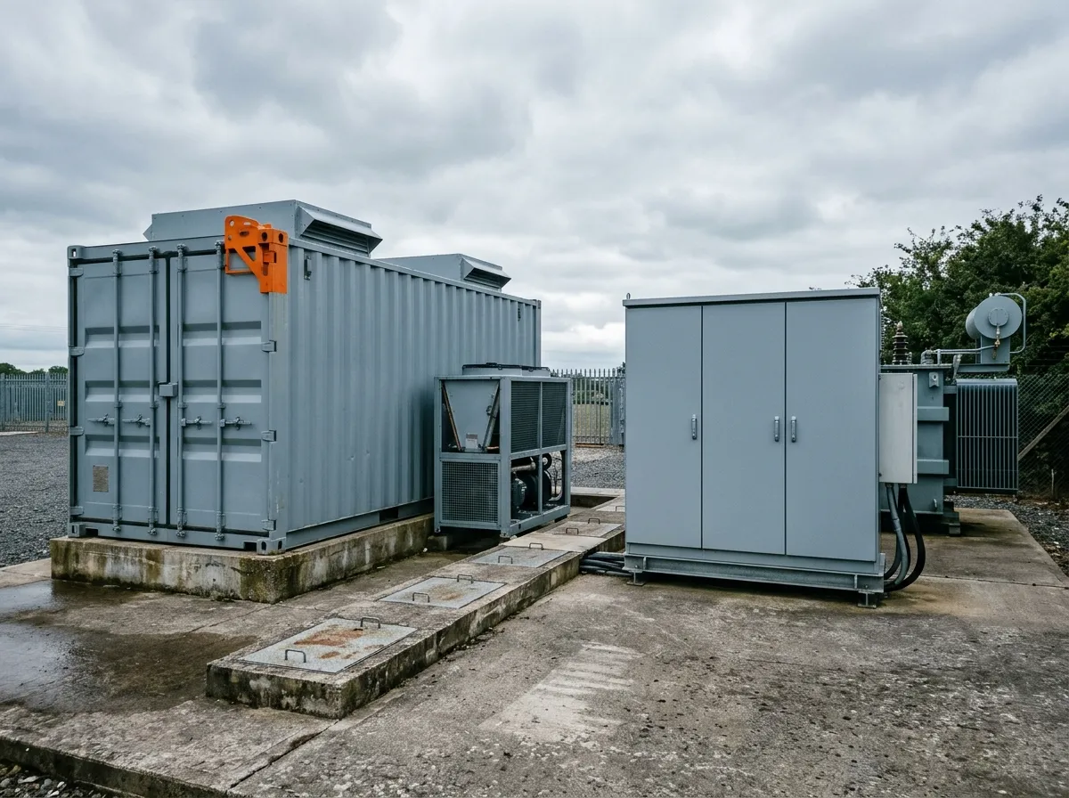
The offer then states the P-Q capability at the point of connection, the reactive power available with the battery at rest, the derating basis and the control modes the converter can follow. Our containerised storage range is specified that way, and the same curves size a utility-scale block where voltage support is part of the revenue case rather than a side effect.
A delivered example in the same C&I segment is the Águeda 500 kW / 1,075 kWh system in Portugal, a commercial site that runs both grid-connected and islanded. If you are working through an interconnection clause, send it to us - the Mvar range, the voltage band and the metering point are enough.