
A grid-forming inverter is an inverter operated in a control mode that regulates its own output voltage and frequency, so that it establishes an AC voltage reference at its terminals rather than following one supplied by the grid. It behaves as a controlled voltage source behind an impedance, while a conventional grid-following inverter injects current into a waveform it measures with a phase-locked loop. Grid-forming capability is a mode, not a product class, and its practical cost is reserved energy, reserved current, a slice of cycle life, and a protection study that has to be redone.
The definition is the easy half. The half worth slowing down for is what follows from it: once an inverter is responsible for the voltage instead of merely reacting to it, the equipment no longer decides its own behavior alone. Three reserves have to be created elsewhere in the system — stored energy that stays uncommitted, current capability the inverter still has after its own duty, and a slice of the battery's cycle life — and then the protection design has to be redone, because the fault no longer comes from a rotating machine. That is why grid-forming is a project decision rather than a datasheet checkbox, and why this entry addresses the EPCs, integrators and technical buyers who decide whether to specify it.
What "Grid-Forming" Actually Describes
On a datasheet, grid-forming usually appears beside volt-var response and voltage ride-through. It does not belong in the same category. Volt-var and ride-through are grid-support functions that a grid-following inverter performs while remaining, electrically, a current source. Grid-forming changes what the inverter is at its terminals.
A conventional grid-following inverter regulates current. It needs an external voltage angle to inject into, which it obtains by tracking the measured grid voltage with a phase-locked loop. That is sound on a stiff grid but fragile on a long feeder with a low short-circuit ratio, where the measured angle moves faster than the loop can follow — the mechanism behind the nuisance trips that weak-grid sites report.
A grid-forming inverter generates the angle instead of measuring it. It regulates its own voltage magnitude and internal angle, presents itself as a controlled voltage source behind an output impedance, and lets power flow follow from the difference between that reference and the network. Because the reference is produced rather than observed, it does not need a live grid to be stable against.
The term is a control behavior, not a product class. Two devices can carry the same label and differ in which modes the manufacturer has validated — grid-connected operation, intentional islanding, black start, parallel operation with generators. The architecture question behind that distinction is how the inverter is coupled to the battery, covered in our entry on AC- and DC-coupled systems.
Grid-Forming and Grid-Following Side by Side
Question | Grid-following inverter | Grid-forming inverter |
|---|---|---|
What it regulates | Output current, in phase with a measured voltage | Output voltage magnitude and angle |
What it needs from the grid | A stable voltage waveform to synchronize to | Nothing beyond a network to exchange power with |
Behavior on a weak feeder | Phase-locked loop can lose lock; trips | Can hold a reference and stabilize locally |
Islanded operation | Cannot establish the island on its own | Can establish it, if the system was designed for it |
Black start | Not a capability of the inverter | Possible when an energy source and transfer equipment are in place |
Fault current | Limited by the inverter's current rating | Still limited by the inverter's current rating |
The last row is not a typo: a grid-forming inverter's fault-current behavior is closer to a grid-following inverter than to a synchronous generator, because both are power-electronics devices with a semiconductor current limit. A rotating machine delivers several times its rated current for a short period, which is what protection engineers expect; an inverter cannot, and that propagates through the whole protection design — see the protection section below. Nor is grid-forming simply better: it answers a different operating condition.
Three Control Families Behind the Label
"Grid-forming" is a family name for at least three control approaches that reach similar behavior by different routes, and which one a supplier has implemented determines what has been validated and tuned.
Droop control is the workhorse. Active power is adjusted in proportion to a frequency deviation and reactive power in proportion to a voltage deviation, so several grid-forming units can share load without a central command channel for every fast transient. It is the basis of the droop-response work Sandia National Laboratories published on grid-forming and grid-following inverter comparison under grid events.
Virtual synchronous machine approaches emulate the inertial response of a rotating machine, so the inverter contributes power during the first moments of a frequency event rather than waiting for a dispatch signal. This is what people mean by synthetic inertia, and why grid-forming is discussed as a partial answer to declining system inertia.
Virtual oscillator control is the third family: the controller is built as a time-domain oscillator whose natural frequency is the nominal grid frequency, so it synchronizes without a phase-locked loop and, unlike a virtual synchronous machine, without an inertia constant. It also differs from droop mainly in the transient rather than the steady state. That gap between controls is why the NERC white paper on grid forming technology — a useful reference because it treats grid-forming controls as a distinct class with their own attributes, benefits and risks rather than as a firmware option — asks generating owners and transmission planners to develop, validate and benchmark positive-sequence and electromagnetic-transient models against each other for every GFM-capable resource. EMT studies are now a routine part of interconnection planning at many utilities, and the Energy Systems Integration Group sets out the modeling workflow in its write-up on simulating systems with high shares of grid-forming inverter-based resources.
Why the Grid-Forming Source Is Usually a Battery
What the three have in common matters more than what separates them. All of them need energy, all of them need current capability, and none of them manufactures either. A PV array alone cannot promise it: its output follows the irradiance, and at night it is not a source at all, and the same is true of a wind farm with no wind. Grid-forming wind and PV have been demonstrated, including onshore wind parks providing grid-forming services, but they remain at pilot and R&D maturity; a source that has to hold a reference through an arbitrary event is where storage wins.
A battery energy storage system can, because it stores energy and a bidirectional power conversion system can move it in either direction. That is why "grid-forming" in a storage project normally means a function of the storage inverter or the battery-side power conversion system, and appears so often beside islanded operation and black start. Black start is not an inverter feature: it is a system capability that needs an energy source, a control hierarchy, transfer equipment and a sequence that was actually tested.
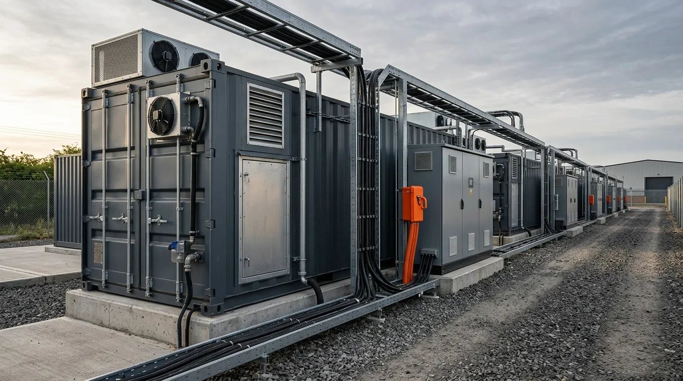
The alternative to a battery is the rotating machine that grid-forming inverters are so often compared with. A synchronous condenser provides real rotating inertia — modest, unless a flywheel is added — and genuine fault current, and utilities install them for exactly those two properties. What it does not provide is stored energy, so it cannot shift a kilowatt-hour from one hour to another, and it costs capital that earns nothing from arbitrage. The question for a storage project is not whether a battery should play this role, but how much of it should.
Sites where islanded operation is not a design goal get the same capability in a narrower form from a hybrid microgrid architecture, where the storage inverter establishes the reference for a defined set of loads instead of a whole network.
What Grid-Forming Costs the Battery and the Power Conversion System
Here the term stops being control theory and becomes a procurement decision: a voltage source has to move power in both directions at short notice, and the room to do that has to exist before the event arrives. Three reserves are created.
Energy headroom. Responding to a frequency event may mean absorbing power as well as delivering it: absorbing needs spare charge capacity, delivering needs stored energy that has not already been committed. So the battery's usable window is narrower than its nameplate suggests — a band of state of charge is reserved for the grid service, above the floor kept for battery health and below the ceiling against overcharge. Both ends of that window are already set by cell behavior, which is what the depth of discharge entry describes; grid-forming duty reserves a slice in the middle as well.
Power and current headroom. Voltage-source behavior is delivered through current, and the inverter's current rating is a hard limit, not a policy. An inverter specified to its rated output for continuous operation may have very little left for the transient a grid event demands, and the same limit caps what it can push into a fault. Sizing must therefore cover the power the site delivers and the power the grid service needs at the same moment — the trade-off the C-rate entry frames from the battery side.
Efficiency, thermal and lifetime. Every extra cycle costs energy in conversion losses, generates heat the thermal system has to remove, and consumes a slice of cycle life — a battery that cycles more often for grid services than for its original duty will live a different life from the one the warranty calculation assumed, and the cooling system has to be sized for the peak duty rather than the average.
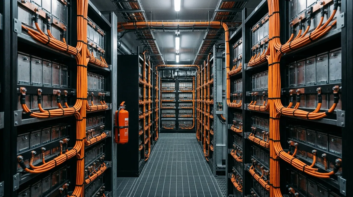
Put plainly: grid-forming is not purchased at the inverter. It is purchased by reserving a slice of the battery's energy, a slice of its power and a slice of its lifetime, and by paying for studies — a constraint that commonly surfaces at commissioning, when the unit is asked to hold a reference it lacks the energy and current to hold.
Protection and Fault Current in Islanded Operation
Protection is the second place the bill arrives. A protection scheme is designed around an assumption about how much current flows into a fault, and on a conventional system that assumption is generous: synchronous machines contribute several times their rated current, and overcurrent relays are set on top of that. An inverter, grid-forming or not, is current-limited by its semiconductors.
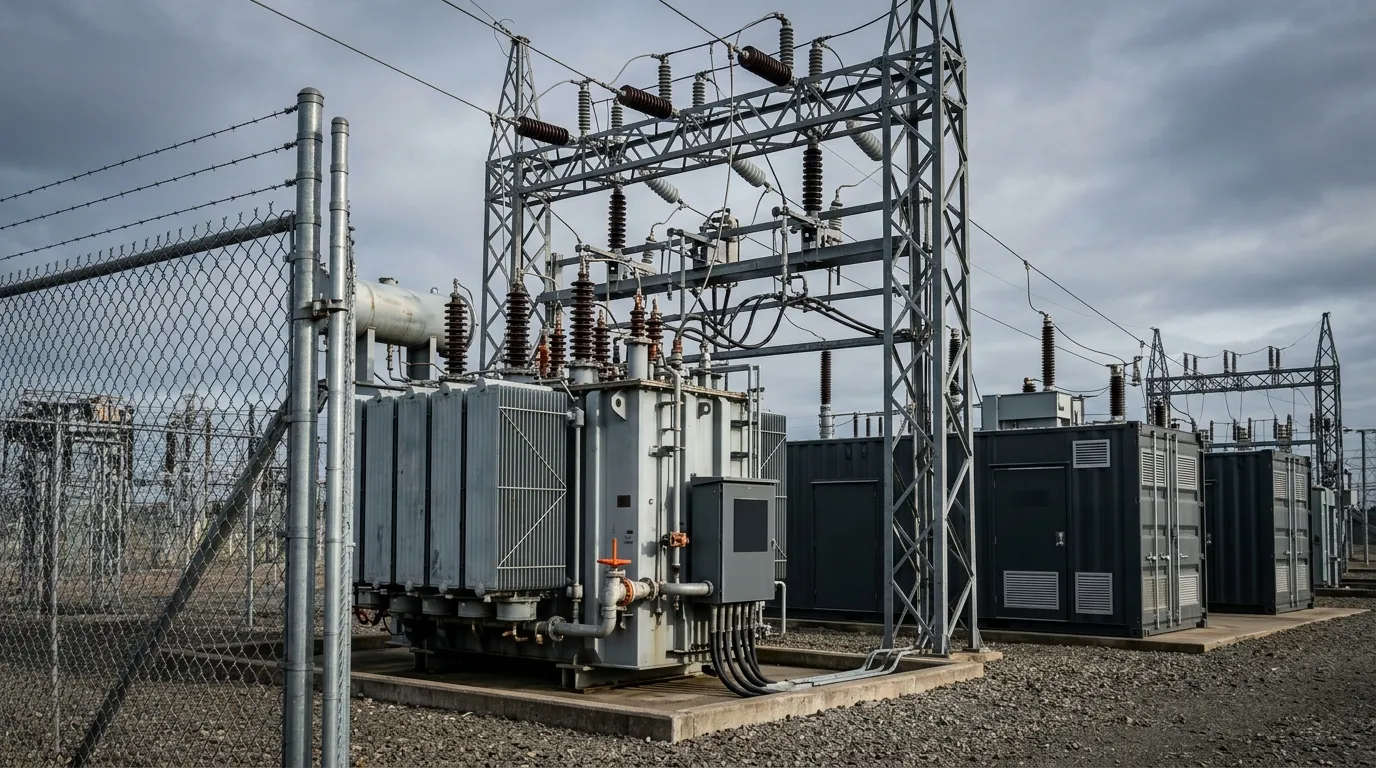
Two consequences follow. Relay pickup settings sized for utility fault current may sit above what an islanded inverter can deliver, so the protection simply does not see the fault. And the available fault current is not the same in both modes: connected to the utility the grid supplies it; islanded, only the inverter does, and the level drops.
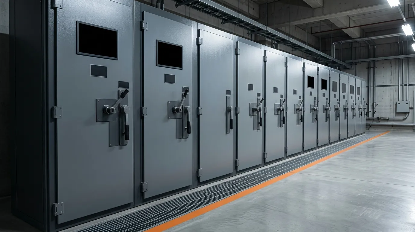
Three areas typically need rework. Relay settings and their selectivity have to be re-derived for the lower current, and where overcurrent protection cannot be made sensitive enough, differential protection on transformers and busbars is the usual substitute. Grounding changes character, because the neutral-ground bonding the utility provides when grid-connected has to be established by the site itself when islanded. And transfer equipment has to match the grounding scheme — a three-pole transfer switch leaves the neutral connected and can create a path a four-pole device would break. Protection coordination therefore belongs in the design phase; a site that leaves it to commissioning has already ordered the switchgear.
What to Ask Before You Specify Grid-Forming
Four questions cover most of the risk, and all four are answerable before equipment is ordered.
What to establish | Why it decides money | Where the answer lives |
|---|---|---|
Which modes has the supplier actually validated, and on which hardware? | The label covers several controls; only validated modes are engineering | The type-test documentation, not the marketing page |
How much energy and current does the grid service reserve? | The reserve is capacity the owner cannot use for arbitrage or backup | The control settings and the energy management strategy |
How does fault current behave in islanded mode? | Relay pickup, grounding and transfer equipment all follow from it | A protection coordination study covering both modes |
Who owns the grid-side requirement, and against which standard? | The interconnection application and the acceptance tests are written against it | The connection agreement and the applicable standard |
The standards are how "validated" turns into evidence. IEEE 2800-2022 sets the minimum interconnection capability and performance requirements for inverter-based resources connecting to transmission and sub-transmission systems, including voltage and frequency ride-through, active and reactive power control and system protection (IEEE 2800-2022). IEEE 1547-2018 covers the distribution-level case, defining interconnection and interoperability requirements and grid-support functions for distributed energy resources (IEEE 1547-2018). Neither is a shopping list, but both are the vocabulary in which a utility's technical requirements are written.
How Hua Power Approaches Grid-Forming Storage Projects
Hua Power is a battery energy storage system integrator founded in 2015 and headquartered in Shenzhen, with more than 400 projects deployed and production capacity above 2.4 GWh, according to the company profile. On a grid-forming project its role is narrow: supply the storage, the power conversion and the control layer that decide whether the site can actually hold a voltage reference, and make the interface to the protection scheme explicit.
Our liquid-cooled container range is specified by usable energy, round-trip efficiency, cycle life and the power margin available for grid services — the four numbers that decide whether the reserved energy and reserved current described above exist in the first place. A container that meets its nameplate capacity but has no margin left after the site's own duty will not hold a reference when asked.
Not every site needs the mode at all: some are specified for duties the grid-forming mode is not being paid for — a contracted frequency-response service at the connection point, engineered against its own grid code and described for grid frequency regulation, or load shifting behind the meter. Where both duties land on one site they compete for the same stored-energy headroom and the same current margin, so they have to be coordinated in the energy management system. Whether the numbers work depends on the site's own load profile and on how much capacity the owner will lock away.