
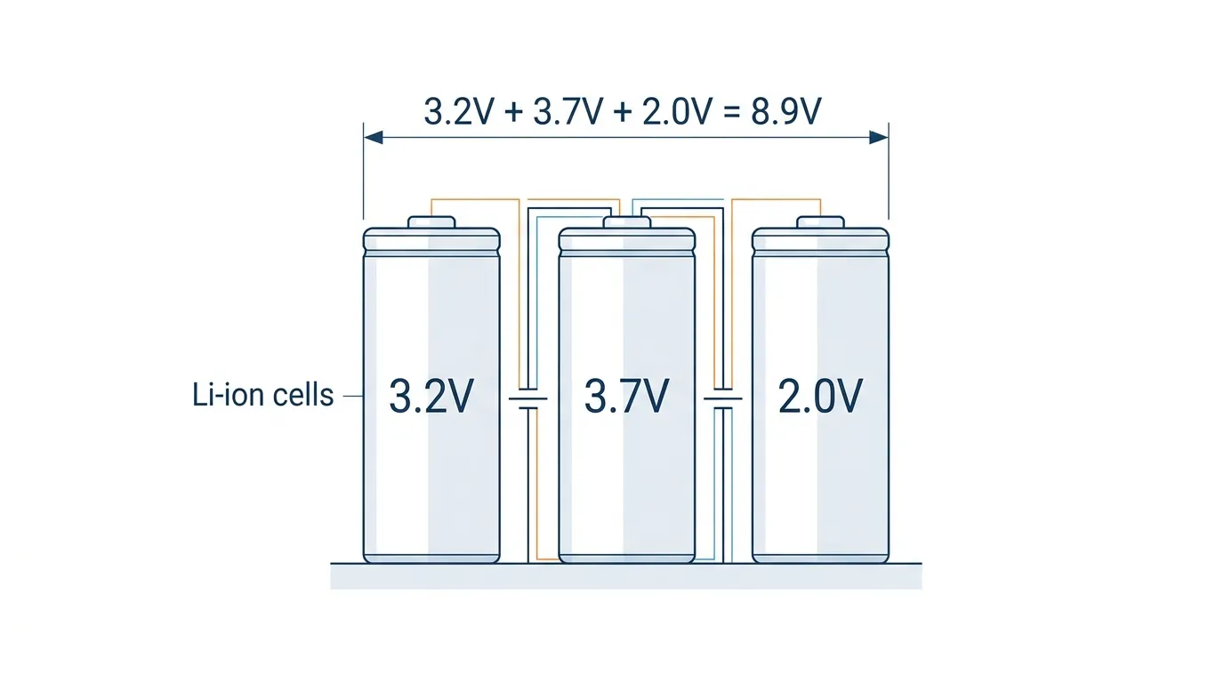
Nominal voltage is the reference voltage assigned to a battery or electrical system — the "nameplate" value used to identify its voltage class. For a lithium-ion battery, nominal voltage is typically 3.6 V or 3.7 V; for a 12 V lead-acid battery, it is 12 V. The actual voltage varies during charge and discharge, but the nominal value serves as the standard reference for system design, component selection, and compatibility checks.
Why Nominal Voltage Matters in Batteries
Every battery has a voltage that changes. A "12 V" lead-acid battery might sit at 12.7 V when fully charged and drop to 10.5 V under heavy discharge. A "3.7 V" lithium-ion cell swings from 4.2 V at full charge to around 3.0 V at cutoff. The nominal voltage sits roughly at the midpoint of this range — it is not a measured value, but a label.
This label is the foundation of battery compatibility. It tells you:
- What charger to use. A 3.7 V nominal lithium cell requires a 4.2 V constant-voltage charger. A 3.2 V nominal LiFePO₄ cell needs a 3.65 V charger. Using the wrong charger because you misread the nominal voltage can damage the cell or create a safety hazard.
- How many cells to put in series. A 48 V battery pack is built from 15 LiFePO₄ cells in series (15 × 3.2 V = 48 V) or 13 NMC cells (13 × 3.7 V ≈ 48.1 V). The choice of series count flows directly from the cell's nominal voltage.
- Which inverter it pairs with. Battery inverters have a defined DC input voltage window. A battery bank whose nominal voltage falls outside that window will not work — the inverter either refuses to start or operates with derated performance.
Tip: When reading a battery datasheet, look for nominal voltage first. It determines almost everything else — charge parameters, inverter compatibility, and whether two batteries can be connected in parallel.
Nominal Voltage vs Operating Voltage vs Rated Voltage
These three terms are often used interchangeably, but each has a distinct meaning. Confusing them leads to specification errors in procurement and system design.
Term | Definition | Example (Li-ion cell) |
|---|---|---|
Nominal Voltage | The reference or "nameplate" voltage of the device | 3.7 V |
Operating Voltage | The actual voltage at any moment during use | 3.2 V – 4.2 V, depending on state of charge |
Rated Voltage | The maximum voltage the equipment is designed to handle safely | 4.2 V (the upper charge limit) |
Nominal voltage is the label (Electrical4U calls it the "named" voltage — from the Latin nomen, meaning name). Operating voltage is what you measure with a multimeter right now. Rated voltage is the safety ceiling: exceed it and the equipment may be damaged.
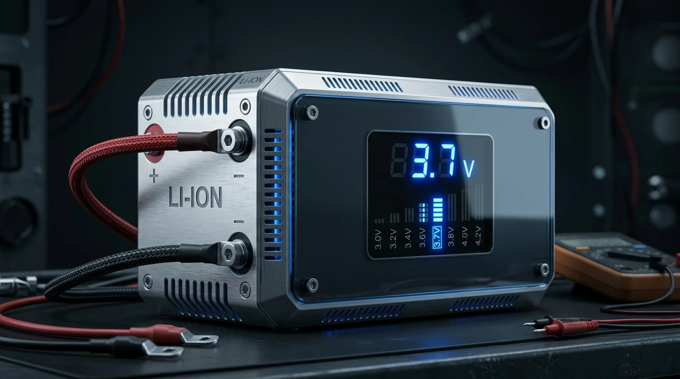
In practice, the gap between nominal and rated voltage is a safety margin. A 132 kV circuit breaker, for example, has a nominal voltage of 132 kV but a rated voltage of 132 kV ± 10% — meaning it can safely operate between roughly 119 kV and 145 kV. The same principle applies at the battery level: a cell rated for 4.2 V maximum voltage is designed around a 3.7 V nominal operating point.
Why this distinction matters in BESS procurement: When a datasheet says "48 V battery," that 48 V is the nominal voltage. The actual operating range might be 42 V to 54 V. If your inverter's DC input range is 44 V to 56 V, you are operating within a narrow 2 V margin at the bottom — a voltage sag under heavy load could trip the inverter. Always check the full operating voltage range, not just the nominal label.
Nominal Voltage by Battery Chemistry
Different battery chemistries have different nominal voltages — a direct consequence of their electrochemical potentials. The table below covers the chemistries most relevant to stationary energy storage.
Battery Chemistry | Nominal Voltage (per cell) | Full Charge Voltage | Discharge Cutoff | Common Applications |
|---|---|---|---|---|
LiFePO₄ (LFP) | 3.2 V | 3.65 V | 2.5 V | C&I storage, residential ESS, telecom backup |
NMC (LiNiMnCoO₂) | 3.6 – 3.7 V | 4.2 V | 3.0 V | EV batteries, high-density portable packs |
LCO (LiCoO₂) | 3.6 V | 4.2 V | 3.0 V | Consumer electronics |
LTO (Li₂TiO₃) | 2.4 V | 2.85 V | 1.5 V | Grid-scale storage, fast-charge applications |
Lead-Acid (flooded/AGM) | 2.0 V | 2.12 V (per cell) | 1.75 V | UPS, backup power, off-grid solar |
Sodium-Ion | ~3.0 V | 3.95 V | ~1.5 V | Emerging grid storage, low-cost stationary applications |

LFP (3.2 V) dominates stationary storage because it offers the best combination of safety, cycle life, and cost. Its lower nominal voltage compared to NMC means a 48 V LiFePO₄ (LFP) pack needs 15 cells in series, while an NMC pack needs only 13 — a small but meaningful difference in BMS channel count and wiring complexity.
The lead-acid nominal voltage of 2.0 V per cell explains why a "12 V" battery contains exactly 6 cells (6 × 2.0 V = 12 V) and a "48 V" lead-acid bank uses 24 cells. This convention dates back over a century and remains embedded in IEC standards for stationary battery systems.
Battery University notes that nominal voltage is one of the most frequently misunderstood battery specifications — precisely because the term "nominal" implies an approximation, yet it anchors every design decision.
Why Nominal Voltage Matters in BESS Design
In a battery energy storage system (BESS), nominal voltage is not just a label on a cell — it is the organizing principle of the entire DC architecture.
1. System Voltage Architecture
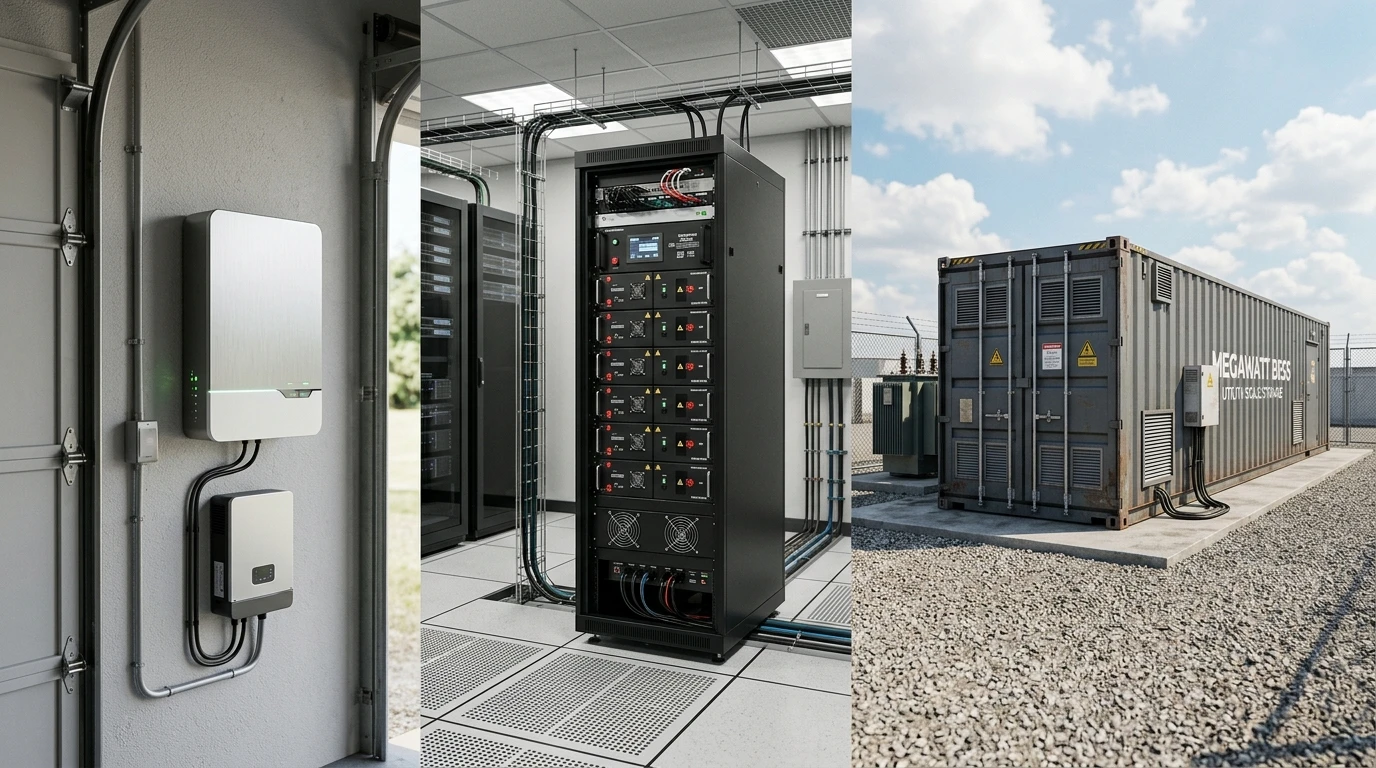
BESS installations are built around standardized DC bus voltages. Common architectures include:
- 48 V DC: Small residential and telecom systems. Typically 15 LFP cells or 13 NMC cells in series.
- 200–400 V DC: Mid-size C&I cabinets. Often 64–128 LFP cells in series, with 2–4 parallel strings.
- 600–900 V DC: Utility-scale containerized systems. Hundreds of cells in series, designed to maximize inverter efficiency at the megawatt level.
- 1000–1500 V DC: The emerging standard for utility-scale PV + storage, enabled by 1500 V-rated inverters.
Each architecture is chosen by multiplying the cell's nominal voltage by the series count. Changing the cell chemistry changes the voltage math — a design built around 3.2 V LFP cells cannot simply swap in 3.7 V NMC cells without recalculating the entire string configuration and BMS parameters.
2. Inverter Compatibility
Battery inverters (PCS) have a defined DC input voltage range, often specified as a nominal DC voltage with a tolerance band. A 400 V nominal PCS might accept 300 V to 500 V DC. The battery string's nominal voltage must sit comfortably within this range, with the full charge voltage below the PCS maximum and the discharge cutoff above the PCS minimum.
When these windows do not align, the result is either a system that refuses to start or one that derates prematurely after only a partial discharge. This is one of the most common integration issues in C&I storage projects — and it is entirely avoidable by matching nominal voltage specifications during the design phase.
3. Parallel String Matching
When multiple battery strings are connected in parallel, their nominal voltages must match. Even a small difference — say, one string at 48 V nominal and another at 51.2 V nominal — causes circulating currents that degrade cells and waste energy. In large BESS installations with multiple racks, this requirement drives careful cell grading and BMS calibration at the factory.
Modules and racks within a single BESS container are always built from the same cell type and the same series count to ensure identical nominal voltage across every parallel path.
4. Voltage Drop and Cable Sizing
At the system level, nominal voltage also determines current levels for a given power rating. A 100 kW system at 400 V DC draws 250 A; the same system at 48 V DC draws over 2,000 A. Lower nominal voltages require much thicker copper busbars and cables, increasing both cost and thermal management burden. This is a core reason why utility-scale BESS designs keep moving toward higher DC voltages — ScienceDirect documents this trend clearly in its engineering reference on nominal voltage.
Practical Implications for System Specifiers
If you are evaluating or procuring a BESS, three checks related to nominal voltage will save you from expensive compatibility errors:
- Match cell nominal voltage to the inverter's DC input window. Do not rely on the battery's "48 V" or "400 V" label alone — get the full operating voltage range and confirm it stays within the inverter's limits at both ends.
- Verify series-parallel configuration. Know how many cells are in series (this determines the pack nominal voltage) and how many strings are in parallel (this determines capacity). These numbers must be consistent across all racks in the installation.
- Check that replacement modules have the same nominal voltage. Even within the same chemistry family, a "48 V" LFP module from one manufacturer may use 15 cells (3.2 V × 15 = 48 V) while another uses 16 cells (3.2 V × 16 = 51.2 V). They are not interchangeable.
Key Takeaways
- Nominal voltage is the reference label — not the actual measured voltage, but the value that defines the battery's voltage class and anchors every design decision.
- Nominal ≠ operating ≠ rated. Operating voltage is what you measure; rated voltage is the safety maximum; nominal voltage is the design reference.
- Chemistry determines nominal voltage at the cell level. LFP (3.2 V), NMC (3.7 V), and lead-acid (2.0 V) each imply different series counts for the same target system voltage.
- At the BESS level, nominal voltage drives architecture. It determines DC bus voltage, inverter compatibility, cable sizing, and whether parallel strings can safely share current.
- Check the full operating range, not just the nominal label. A "48 V" battery that actually operates from 42 V to 54 V may not work with a 44–56 V inverter.